volkswagen Workshop Repair Guides

Volkswagen Workshop Service and Repair Manuals

Checking coolant temperature sender > < Checking engine operating mode
Digifant injection and ignition system (4-valve)
Digifant injection and ignition system
Checking throttle valve potentiometer

Special tools, testers and auxiliary items

  • ◆ Fault reader V.A.G 1551 or vehicle system tester V.A.G 1552 with
         ▸ 07.93: Cable V.A.G 1551/1
         08.93 ▸: Cable V.A.G 1551/3
  • ◆ Test box V.A.G 1598/18
  • ◆ Hand multimeter V.A.G 1526 or multimeter V.A.G 1715
  • ◆ Adapter set V.A.G 1594
  • ◆ Current flow diagram

Test sequence

  • ‒ Connect the fault reader V.A.G 1551 (V.A.G 1552) and with ignition switched on select engine electronics control unit with the "Address word" 01.
    (Connecting fault reader and selecting engine electronics control unit .)
  • ‒ When the engine electronics control unit registers, note the control unit version.
 
→ Indicated on display:
Rapid data transfer     HELP
Select function XX
  • ‒ Input 08 for "Read measured value block" function and confirm with Q key.
 
→ Indicated on display:
Read measured value block     HELP
Input display group number XX
  • ‒ Enter "Display group number" and confirm with Q key.
         Digifant 3.0 = 02
         Digifant 3.2 = 03
 
→ Indicated on display:
(1...4 = Display zones)
Read measured value block 2 (3)     ⇒
     1     2     3     4
  • ‒ Read-off throttle valve angle in display zone 3.
         Specification: 0 <°
  • ‒ Slowly open throttle valve and watch angle display in display zone 3.
    The figure must increase uniformly over
         the complete range.

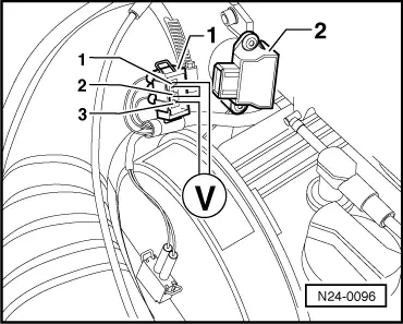
Note:

The displayed figure is dependent on the tolerances of the throttle valve potentiometer and does not correspond to the actual opening angle. The maximum permissible displayed figure is 86 <°.

If the figure does not increase uniformly:

  • ‒ Replace throttle valve potentiometer (G69).

If the display shows constant 0 <° or approx. 90 <°:

Display

Cause

Continuation of check

0 <°

Open circuit or short to earth

=> Page 24-46

approx.
90 <°

Short to positive

=> Page 24-47

Continuation of check when display 0 <°:

 
N24-0096
  • ‒ → Pull 3 pin connector -1- off throttle valve potentiometer -2-.
  • ‒ Bridge contacts 1+2 of connector with aux. cables from V.A.G 1594 and observe display.

Display 90 <°:

  • ‒ Replace throttle valve potentiometer -2-.

Display 0 <°:

  • ‒ Check voltage between contacts 1+3 on plug.
         Specification: approx. 5 V
  • ‒ Press ⇒key.
 
N24-0094
  • ‒ Input 06 for "End output" and confirm with Q key.
  • ‒ Switch off ignition.
  • ‒ → Connect test box V.A.G 1598/18 to control unit wiring loom.

If voltage of about 5 V was present:

  • ‒ Check wire between test box socket 40+3 pin connector contact 2 for open circuit according to current flow diagram.
         Wire resistance: max. 1.5 ω
  • ‒ Additionally check wire for short to earth.
         Specification: ∞ω

If no voltage was present:

  • ‒ Check wire between test box socket 41+ 3 pin connector contact 1 also socket 33+contact 3 for open circuit according to current flow diagram.
         Wire resistance: max. 1.5 ω

If no wiring fault is detected:

 
N24-0097
  • ‒ Renew Digifant control unit (J169)
    , item 11 .

Continuation of check when display = approx. 90 <°:

  • ‒ → Pull 3 pin connector -1- off throttle valve potentiometer -2-.

Display 0 <°:

  • ‒ Replace throttle valve potentiometer -2-.

Display 90 <°:

  • ‒ Check voltage between contacts 1+2 on connector and note.
  • ‒ Press ⇒key.
  • ‒ Input 06 for "End output" and confirm with Q key.
  • ‒ Switch off ignition.
  • ‒ Pull connector off Digifant control unit.

If voltage of about 5 V was present:

  • ‒ Check wiring at 3 pin connector contacts 1+2 for short to one another according to current flow diagram.

If the voltage was approx. battery voltage:

  • ‒ Check wire at 3 pin connector contact 2 for short to battery positive according to current flow diagram.

If no wiring fault is detected:

  • ‒ Renew Digifant control unit (J169)
    , item 11 .

Checking coolant temperature sender > < Checking engine operating mode