volkswagen Workshop Repair Guides

Volkswagen Workshop Service and Repair Manuals

Read measured value block and basic settings > < Fault table Digifant 3.2
Digifant injection and ignition system (4-valve)
Self diagnosis
Final control diagnosis

The final control diagnosis activates the following components in the stated sequence:

1. Fuel pump relay (J17)

2. Idling speed stabilisation valve (N71)

3. Activated charcoal filter solenoid valve 1 (N80)

Special tools, testers and auxiliary items

  • ◆ Fault reader V.A.G 1551 or vehicle system tester V.A.G 1552 with
         ▸ 07.93: Cable V.A.G 1551/1
         08.93 ▸: Cable V.A.G 1551/3
  • ◆ Test box V.A.G 1598/18
  • ◆ Hand multimeter V.A.G 1526 or multimeter V.A.G 1715
  • ◆ Diode test lamp V.A.G 1527
  • ◆ Adapter set V.A.G 1594
  • ◆ Measuring cable V.A.G 1501
  • ◆ Current flow diagram

Work sequence

  • ‒ Connect the fault reader V.A.G 1551 (V.A.G 1552) and with ignition switched on select engine electronics control unit with the "Address word" 01.
    (Connecting fault reader and selecting engine electronics control unit .)
 
→ Indicated on display:
Rapid data transfer     HELP
Select function XX
  • ‒ Operate fault reader taking into account the information on the display:
  • ‒ Input 03 for "Final control diagnosis" function.
 
→ Indicated on display:
Rapid data transfer     Q
03 Final control diagnosis

Actuate fuel pump relay (J17):

  • ‒ Confirm input with Q key.
 
→ Indicated on display:
Final control diagnosis     ⇒
Fuel pump relay J17
  • The fuel pump relay (on the relay plate with fuse box, relay position 12) must click until switching to the next final control by pressing the ⇒key.

Note:

During the activation of the fuel pump relay the fuel pump must be heard to run at intervals.

If the relay does not click:

  • ‒ Check fuel pump relay:

=> Current flow diagrams, Electrical fault finding and Fitting locations, Fuel supply system

Activate idling stabilization valve (N71):

  • ‒ Press ⇒key.
 
→ Indicated on display:
Final control diagnosis     ⇒
Idling stabilization valve N71
  • The idling stabilization valve must click, until activating the next final control by pressing the ⇒button.

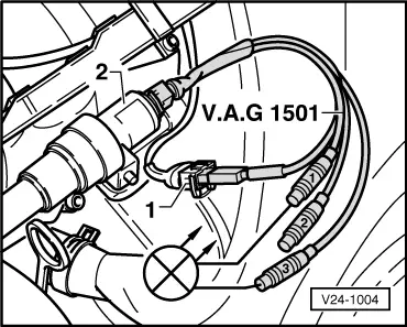
If the idling stabilization valve does not click:

  • ‒ To continue check => Page 01-27 .

Activate solenoid valve 1 for activated charcoal filter (N80):

  • ‒ Press ⇒key.
 
→ Indicated on display:
Final control diagnosis     ⇒
Activ. charcoal filter solenoid valve 1     -N80
  • The solenoid valve (right suspension turret) must click until the final control diagnosis is ended by pressing the ⇒key.

If the solenoid valve does not click:

  • ‒ Continue check => Page 01-29 .

Note:

After completion of the final control diagnosis input 06 for "End output" function and confirm with Q key. Then the ignition must be switched off. If the ignition is not switched off before attempting to start, the engine will not start, as the injectors and the ignition transformer will not be activated.

Continuation of check when idling stabilization valve does not click:
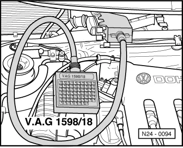
  • ‒ Remove intake manifold cover.
 
V24-1004
  • ‒ → Pull plug -1- off valve -2- and connect measuring cable V.A.G 1501 to valve and wiring loom.
  • ‒ Connect diode test lamp V.A.G 1527 with adapters from V.A.G 1594 to connectors 1 and 3 of the measuring cable.
         LED must flash at regular intervals

LED flashes:

  • ‒ Proceed with final control diagnosis until completed.
  • ‒ Switch off ignition.
  • ‒ Renew idling stabilization valve.

LED does not flash:

  • ‒ Proceed with final control diagnosis until completed.
  • ‒ Switch off ignition.
 
N24-0094
  • ‒ → Connect test box V.A.G 1598/18 to control unit wiring loom.
  • ‒ Check wire between test box socket 27+3 pin connector contact 3 according to current flow diagram for open circuit.
         Wire resistance: max. 1.5 ω
  • ‒ Also check wire for short to battery positive and earth.
         Specification: ∞ω
  • ‒ Check wire between 3 pin connector contact 1 and relay plate according to current flow diagram for open circuit.
         Wire resistance: max. 1.5 ω

If no wiring fault is detected:

  • ‒ Renew Digifant control unit (J169)
    , item 11 .

Continuation of check when the activated charcoal filter solenoid 1 does not click:
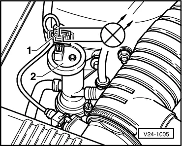
 
V24-1005
  • ‒ → Pull connector -1- off valve -2- and connect diode test lamp V.A.G 1527 with aux. cables from V.A.G 1594 to disconnected connector.
         The LED must flash

LED flashes:

  • ‒ Proceed with final control diagnosis until completed.
  • ‒ Switch off ignition.
  • ‒ Renew solenoid valve.

LED does not flash:

  • ‒ Proceed with final control diagnosis until completed.
  • ‒ Switch off ignition.
 
N24-0094
  • ‒ → Connect test box V.A.G 1598/18 to control unit wiring loom.
  • ‒ Check wire between test box socket 31+2 pin connector contact 1 according to current flow diagram for open circuit.
         Wire resistance: max. 1.5 ω
  • ‒ Also check wire for short to battery positive and earth.
         Specification: ∞ω
  • ‒ Check wire between 2 pin connector contact 2 and relay plate according to current flow diagram for open circuit.
         Wire resistance: max. 1.5 ω

If no wiring fault is detected:

  • ‒ Renew Digifant control unit (J169)
    , item 11 .

Read measured value block and basic settings > < Fault table Digifant 3.2