volkswagen Workshop Repair Guides

Volkswagen Workshop Service and Repair Manuals

Test table > < Test table
Ecomatic Self-diagnosis
Gearbox: Electrical test
  • ‒ Perform only the recommended test steps listed in the fault table (targeted entry).
  • ‒ Perform all the measures stated in the column "Rectifying fault".

Notes:

  • ◆ Use the hand multimeter V.A.G 1526 for testing.
  • ◆ The specified values relate to an ambient temperature from 0 °C...40 °C.
  • ◆ If the readings obtained differ from the specified values, determine fault on the basis of the current flow diagram.
  • ◆ If the readings obtained differ only slightly from the specified values, clean sockets and connectors of the testers and test leads and repeat test. Before replacing the particular components, test wiring and connections and, particularly if specified values are below 10 ω, repeat the resistance measurement on component.
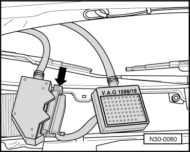
  • ◆ To connect the testers use test box V.A.G 1598/18 and aux. cables from V.A.G 1594.
  • ◆ The contact numbers of the connector and the socket numbers in the test box V.A.G 1598/18 are identical .
Warning!
Select the appropriate measuring range at the tester before connecting the test leads to avoid damaging the electronic components.

Test requirements:

  • ● Battery voltage in order.
  • ● Fuses No. 14, 15 and 21 OK.
  • ● Earth connections in order:
  • The earth connection point is located on the left next to the relay plate.
  • Check battery earth strap and earth strap between battery and gearbox.
 
N30-0060
  • ‒ Switch off ignition for all test steps, release multi-pin connector from clutch electronics control unit -J327- and then pull off (the control unit is located on right in plenum chamber below the split water deflector). Connect test box V.A.G 1598/18 to the wiring loom connector and lock in direction of arrow.
  • ‒ If the readings obtained differ from the specified values, perform measures for rectifying faults in right-hand column of test table => from Page 01-92 .
  • ‒ Using the test box 1598/18 all wiring from control unit -J327- can be checked for continuity or open circuit according to current flow diagram.

Ecomatic control unit -J327- multi-pin connector, 68-pin (sockets on V.A.G 1598/18)

1 - Earth (terminal 31)
2 - Exhauster relay -J318-
3 - Fuel cut-off valve N109-
4 - Ecomatic warning lamp -K110-
5 - Generator -K2- and oil pressure -K3- warning lamps
6 - Vacant
7 - Vacant
8 - K-wire for diagnosis
9 - Clutch positioner vacuum valve -N183-
10 - Engine speed sender -G28- (screening)
11 - Clutch movement sender -G162- (wear)
12 - Clutch movement sender -G162- (5 volts)
13 - Gearbox speed sender -G38-
14 - Gearbox speed sender -G38- (input)
15 - Gear recognition switch -F208- (2nd and 5th gear)
16 - Load signal potentiometer -G157- (wear)
17 - Load signal potentiometer -G157- (5 volts)
18 - Gearshift switch -F191-
19 - Clutch system vacuum valve -F210-
20 - Brake light switch -F- (signal)
21 - Door contact switch -F2-
22 - Terminal 15
23 - Terminal 30

24 - Priority switching valve -N185-
25 - Starter relay -J53-
26 - Gearshift indicator warning lamp -K48-
27 - Ecomatic automatic override warning lamp -K111-
28 - Steering hydraulics relay -J320-
29 - Speedometer sender -G22-
30 - Diesel engine inhibitor switch -F207-
31 - Clutch positioner vent valve -N184-
32 - Engine speed sender -G28-
33 - Engine speed sender -G28- (input)
34 - Clutch movement sender -G162- earth
35 - Coolant temperature sender -G62-
36 - Gearbox speed sender -G38- (screening)
37 - Gear recognition switch -F208- (1st and 4th gears)
38 - Gear recognition switch -F208- (Neutral and 3rd gear)
39 - Load signal potentiometer -G157- earth
40 - Gear recognition switch (reverse gear) -F208-
41 - Brake servo vacuum switch -F190-
42 - Ecomatic switch -E163-
43 - Gear monitoring switch -F209-
44 - Terminal 50
45 - Terminal 86
46 - Up to socket 681)

1)     Sockets 46 to 68 are vacant

Test table > < Test table