
Golf Mk3
|
Mono-Motronic injection and ignition system
Checking and adjusting idling switch
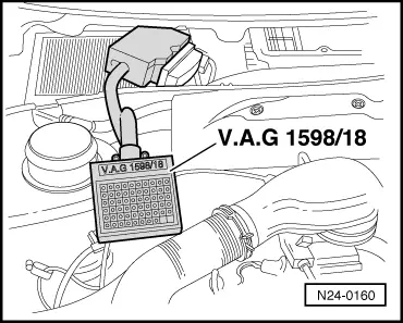
Engine code ABD Engine codes ABU, AEA Special tools, testers and auxiliary items
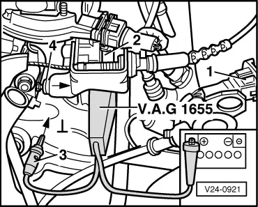
Test conditions
Checking and adjusting idling switch (F60) gap Notes:
Test sequence
|
 |
|
Note: The injection unit is not connected to vehicle earth. |
 |
|
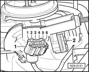
Checking function
Engine codes ABU, AEA Special tools, testers and auxiliary items
Notes:
|
| → Indicated on display: |
|
||
|
| → Indicated on display: |
|
||
|
| →
Indicated on display: (1...4 = Display zones) |
|
|||||||||
|
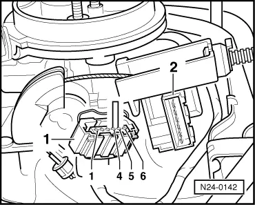
Checking function
If the specifications are not attained:
Continuation of check when display = always 1: |
 |
|
Display 0:
Display 1:
If no fault in wire is detected:
Continuation of check when display = always 0: |
 |
|
Display 1:
Display 0:
|
 |
|
If no wiring fault is detected:
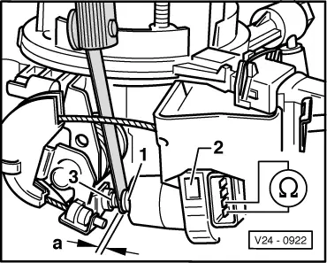
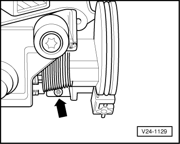
Checking adjustment Note: The adjustment of the idling switch must be performed in function "04 Basic setting" -positioner fully extended-. If the basic setting has to be exited for checking the wiring, the system must be brought back to basic setting with ignition switched on. |
| →
Indicated on display: (1...4 = Display zones) |
|
||
|
| →
Indicated on display: (1...10 = Display zones) |
|
||
If the specification is not obtained:
|
 |
|
Note: If during adjustment the throttle valve is opened to gain access to the screw, the control unit will move the throttle valve positioner back. To move the positioner fully out again, the function basic setting must be selected again.
If it is not possible to adjust to specification:
|