volkswagen Workshop Repair Guides

Volkswagen Workshop Service and Repair Manuals

Checking injector > < Checking coolant temperature sender
Mono Motronic injection and ignition system
Mono-Motronic injection and ignition system
Checking intake air temperature sender

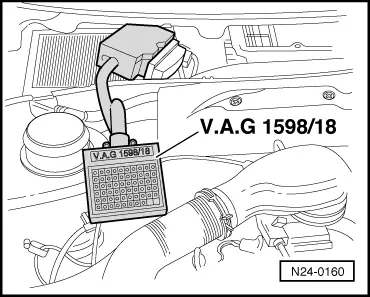
Special tools, testers and auxiliary items

  • ◆ Fault reader V.A.G 1551 or vehicle system tester V.A.G 1552 with
         ▸ 07.93: Cable V.A.G 1551/1
         08.93 ▸: Cable V.A.G 1551/3
  • ◆ Test box V.A.G 1598/18
  • ◆ Hand multimeter V.A.G 1526 or multimeter V.A.G 1715
  • ◆ Adapter set V.A.G 1594
  • ◆ Current flow diagram
  • ◆ Chilling spray (commercially available)

Test sequence

Engine codes ABD 02.93 ▸, ABU, AEA

Engine codes ABD ▸01.93

  • ‒ Connect fault reader V.A.G 1551 (V.A.G 1552) and select engine electronics control unit (address word 01); carry out selection with ignition switched on.
    => Page 01-4
 
→ Indicated on display:
Rapid data transfer     HELP
Select function XX
  • ‒ Input 08 for "Read measured value block" function and confirm with Q.
 
→ Indicated on display:
Read measured value block     HELP
Input display group number XX
  • ‒ Input 02 for "Display group number" and confirm with Q.
 
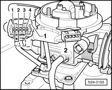
→ Indicated on display:
(1...4 = Display zones)
Read measured value block 2     ⇒
     1     2     3     4
  • ‒ Note intake air temperature figure in display zone 4.

Display

Cause

Continuation of check

Approx. -55 °C

Open circuit or short to positive

=> Page 24-72

Approx. 130 °C or higher

Short to earth

=> Page 24-73

Approx. ambient temperature1)

---

=> Page 24-74

     1)     If a temperature is displayed which deviates greatly from the ambient temperature of the sender, check sender wiring for transfer resistances.

Continuation of check when display = -55 °C:

  • ‒ Remove air intake elbow.
 
N24-0193
  • ‒ → Pull 4 pin connector -1- off injection unit -2- (engine code ABD: Front connector).
  • ‒ Bridge following contacts on connector with aux. cables from V.A.G 1594:
         Engine code ABD: Contacts 1+4
         (broken line)
         Engine codes ABU, AEA: Contacts 1+2

Display approx. 130 °C or higher:

  • ‒ Replace injector bracket with intake air temperature sender (G42) , item 7 .

Display approx. -55 °C:

  • ‒ Press ⇒ button.
 
N24-0160
  • ‒ Input 06 for "End output" and confirm with Q.
  • ‒ Switch off ignition
  • ‒ → Connect test box V.A.G 1598/18 to control unit wiring loom.
  • ‒ Check wire between test box socket 43+4 pin connector
         Engine code ABD: Contact 4
         Engine code ABU, AEA: Contact 2
    for open circuit according to current flow diagram.
         Wire resistance: Max. 1.5 ω
  • ‒ Additionally check wire for short to battery positive.
         Specification: ∞ω
  • ‒ Check wire between test box socket 17+4 pin connector contact 1 for open circuit according to current flow diagram.
         Wire resistance: Max. 1.5 ω

If no fault in wire is detected:

  • ‒ Renew Mono Motronic control unit (J257)
    , item 2 .
 
N24-0149

Continuation of check when display = 130 °C or higher:

  • ‒ Remove air intake elbow.
  • ‒ → Pull 4 pin connector -1- off injection unit -2- (engine code ABD: Front connector).

Display approx. -55 °C:

  • ‒ Replace injector bracket with intake air temperature sender (G42) , item 7 .

Display approx. 130 °C or higher:

  • ‒ Press ⇒ button.
  • ‒ Input 06 for "End output" and confirm with Q.
  • ‒ Switch off ignition
  • ‒ Pull connector off Mono Motronic control unit.
  • ‒ Check wiring to control unit connector at 4 pin connector
         Engine code ABD: Contact 4
         Engine code ABU, AEA: Contact 2
    for short to wire contact 1 and to vehicle earth.
         Specification: ∞ω

If no wiring fault is detected:

  • ‒ Renew Mono Motronic control unit (J257)
    , item 2 .

Continuation of check when display = ambient temperature:

  • ‒ Remove air intake elbow.
  • ‒ Note intake air temperature figure in display zone 4.
 
N24-0150
  • ‒ → Spray sender arrow with a commercial chilling spray and at the same time observe the temperature figure. The temperature figure must
         decrease.
  • ‒ Press ⇒ button.
  • ‒ Input 06 for "End output" and confirm with Q.

Engine code ABD ▸ 01.93

  • ‒ Remove air cleaner cover.
  • ‒ Connect fault reader V.A.G 1551 (V.A.G 1552) and select engine electronics control unit (address word 01); carry out selection at idling.
    => Page 01-4
 
→ Indicated on display:
Rapid data transfer     HELP
Select function XX
  • ‒ Input 08 for "Read measured value block" function and confirm with Q.
 
→ Indicated on display:
Read measured value block     HELP
Input display group number XX
  • ‒ Input 00 for "Display group number" and confirm with Q.
 
→ Indicated on display:
(1...10 = Display zones)
Read measured value block     0     ⇒
     1     2     3     4     5     6     7     8     9     10
  • ‒ Note intake air temperature figure in display zone 4.
 
N24-0198
  • ‒ → Spray sender -arrow- with a commercial chilling spray and at the same time observe the temperature figure. The temperature figure must
         increase.

If the display changes:

  • ‒ Press ⇒ button.
  • ‒ Input 06 for "End output" and confirm with Q.

If the display does not change:

  • ‒ Press ⇒ button.
  • ‒ Input 06 for "End output" and confirm with Q.
 
N24-0194
  • ‒ Switch off ignition
  • ‒ → Pull 4 pin connector -1- off injection unit -2-.
  • ‒ Check resistance between contacts 1+4 at socket.
         Specification , Fig. 1
  • ‒ Spray sender with chilling agent and observe resistance. The resistance must
         increase.

If the resistance values are not attained or no change is detected:

  • ‒ Replace injector bracket with intake air temperature sender (G42) , item 7 .

If the specifications are attained:

 
N24-0160
  • ‒ → Connect test box V.A.G 1598/18 to control unit wiring loom.
  • ‒ Check wire between test box socket 43+4 pin connector contact 2 for open circuit according to current flow diagram.
         Wire resistance: Max. 1.5 ω
  • ‒ Additionally check wire for short to battery positive, to wire contact 1 and to vehicle earth.
         Specification: ∞ω
  • ‒ Check wire between test box socket 17+4 pin connector contact 1 for open circuit according to current flow diagram.
         Wire resistance: Max. 1.5 ω

If no fault in wire is detected:

  • ‒ Renew Mono Motronic control unit (J257)
    , item 2 .

Checking injector > < Checking coolant temperature sender