volkswagen Workshop Repair Guides

Volkswagen Workshop Service and Repair Manuals

Dismantling and assembling intake manifold > < Fitting locations overview
Mono Motronic injection and ignition system
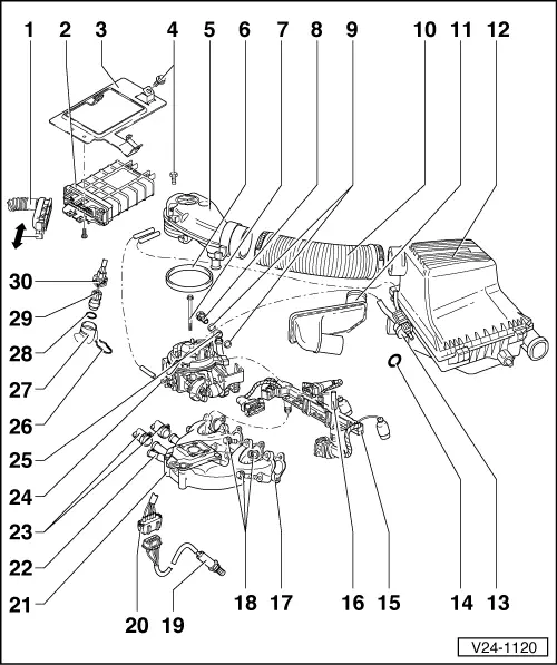
Mono-Motronic injection and ignition system
Servicing injection part

Servicing ignition part

=> Repair group 28

Notes:

  • ◆ The control unit for the fuel injection and ignition system is equipped with a fault memory. Before carrying out repairs, adjustment work and fault finding the fault memory must be interrogated and the vacuum connections checked (outside air).
  • ◆ Components marked with * are checked via the self diagnosis.
    , interrogating fault memory
  • ◆ Components marked with ** are checked via the final control control diagnosis => Page 01-19 .
  • ◆ Always renew spring-type hose clips with screw-type hose clips.
  • ◆ For trouble-free operation of the electrical components a voltage of at least 11.5 V is necessary.
  • ◆ If the engine starts, runs for a short period and then stops, after fault finding, repairs or component tests, then the fault may lie with the immobilizer which is blocking the engine control unit. The fault memory must be interrogated and if necessary the control unit matched => Page 24-87 .
  • ◆ During some checks it can happen that the control unit will recognise and store a fault. Therefore after completing all checks and repairs the fault memory must be interrogated and if necessary erased.
    => Page 01-7 , interrogating fault memory
  • ◆ Do not use sealants containing silicone. Particles of silicone drawn into the engine, will not be burnt in the engine and damage the Lambda probe.

Safety precautions

Rules for cleanliness => Page 24-30

Technical data => Page 24-31

Checking intake air system for leaks (unmetered air) => Page 24-96 .

Routing/securing engine wiring loom:

     Engine code ABU

     Engine code AEA

 
V24-1120
  • Connector
    • ◆ Only disconnect or connect with ignition switched off
    • ◆ Unlatch to disconnect
  • Mono Motronic control unit (J257)*
    • ◆ For injection system, Lambda regulation, activated charcoal filter solenoid valve, speed governing via fuel pump relay, intake air preheating control, ignition and self diagnosis
    • ◆ Location: in plenum chamber, right
    • Vehicles 10.94 ▸
    • ◆ On replacement, the control unit must be matched to the electronic immobilizer => Page 24-87
  • Retainer
  • 10 Nm
 
V24-1120
  • Air intake elbow
  • Seal
  • 15 Nm
  • Banjo bolt, 25 Nm
    • ◆ Engine code ABD
    • ◆ Engine code ABU, AEA: Connecting pipe
  • Seal
    • ◆ Renew
  • Intake hose
    • ◆ Renew O rings if damaged
  • Warm air intake
    • ◆ From warm air collector on exhaust manifold
  • Air cleaner
    • ◆ Dismantling and assembling => Page 24-14
    • ◆ ▸ 07.92 Round air cleaner; dismantling and assembling
      => Page 24-16
 
V24-1120
  • Activated charcoal filter solenoid valve 1 (N80)
    • ◆ Activated charcoal filter system

=> Repair group 20, removing and installing parts of the fuel supply system, removing and installing parts of the activated charcoal filter system

  • Retaining ring
  • Cable guide
    • ◆ To remove pull out spreader pin -16- (if necessary screw in self tapping screw to do this)
    • ◆ Engine code ABU, AEA: without multi-pin connector
  • Spreader pin
  • Seal
    • ◆ Renew
  • 25 Nm
 
V24-1120
  • Lambda probe (G39)*, 55 Nm
    • ◆ Location: in catalyst, front exhaust pipe or in front silencer
    • ◆ Grease only the threads with "G5"; "G5" must not get into the slots on the probe body
    • ◆ Checking Lambda probe and Lambda control
      => Page 24-34
    • ◆ Checking probe heating voltage supply => Page 24-41
    • ◆ Check probe heating for continuity
  • 4 pin connector
    • ◆ For Lambda probe and probe heating
    • ◆ On the engine console, right
  • Intake manifold
  • Vacuum connection
    • ◆ To brake servo
 
V24-1120
  • To thermostat housing
    • ◆ Engine code ABU, AEA: one connection at centre of intake manifold
  • Injection unit
    • ◆ Servicing
      Engine code ABD
      => Page 24-23
  • Fuel pipe
  • Retaining clip
  • Thermostat housing
  • O ring
    • ◆ Renew
 
V24-1120
  • Coolant temperature sender (G62)*
    • ◆ With coolant temperature gauge sender (G2)
    • ◆ If necessary before removing, release pressure from cooling system
    • ◆ Identification: yellow ring
    • ◆ Checking
    • ◆ Resistance graph
      , Fig. 1
  • Connector

Dismantling and assembling intake manifold > < Fitting locations overview