volkswagen Workshop Repair Guides

Volkswagen Workshop Service and Repair Manuals

Interrogating fault memory > < Technical data of self-diagnosis
Mono Motronic injection and ignition system
Self-diagnosis
Connecting fault reader V.A.G 1551 and selecting engine electronics control unit

Special tools, testers and auxiliary items
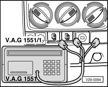
Vehicles ▸ 07.93

  • ◆ Fault reader V.A.G 1551 with cable V.A.G 1551/1
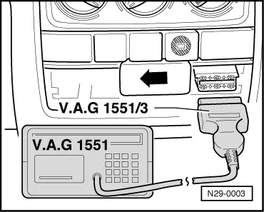
Vehicles 08.93▸

  • ◆ Fault reader V.A.G 1551 with cable V.A.G 1551/3

Note:

The vehicle system tester V.A.G 1552 can be used instead of the fault reader V.A.G 1551, however a print-out is not possible.

Check conditions

  • ● Fuse 21 or 22 OK.
  • ● Battery voltage at least 11 V
  • ● Earth connections on gearbox or engine OK.
  • ● Air conditioner switched off

Work sequence

 
V29-0064

Vehicles ▸ 07.93

  • ‒ → Unclip covers for diagnostic connections below the heating/ventilation controls.
  • ‒ Connect fault reader (or vehicle system tester) with cable V.A.G 1551/1 as follows:
  • ‒ First connect black plug for the fault reader voltage supply to black diagnostic socket.
  • ‒ Connect white plug to white diagnostic socket. (The blue plug is not required.)

Vehicles 08.93 ▸

 
N29-0003
  • ‒ → Open ashtray, remove if necessary and slide cover for diagnostic connections to left -arrow-.
  • ‒ Connect fault reader (or vehicle system tester) with cable V.A.G 1551/3.

After the fault reader has been connected:

  • ‒ Depending upon desired function:
    Switch on ignition
         or
    Start engine , Table "Selectable functions".

Notes:

  • ◆ If the display does not indicate as described in the work sequence:

=> Fault reader operating instructions

  • ◆ If due to an input fault "Fault in the data transfer!" is displayed, pull wire off fault reader, reconnect and repeat work step.
  • ‒ Operate fault reader taking into account the information on the display:
  • ‒ Input 1 for "Rapid data transfer".
  • ‒ Input 01 for address word "Engine electronics" and confirm with Q.
 
→ The fault reader display will show the control unit identification, e.g.:
1 HO 907 311A 1.8ltr.     R4 MONO     D11 ⇒
Coding 01
  • ◆ 1HO 907 311A = Part No. of the control unit
  • ◆ 1.8 ltr. = Engine capacity
  • ◆ R4 = Type of engine (4 Cyl. in-line engine)
  • ◆ MONO = Injection system (Mono-Motronic)
  • ◆ D11 = Programme level number
  • ◆ Coding 01 = Coding variants
  • ‒ Press ⇒ key.
 
→ Indicated on display:
Rapid data transfer     HELP
Select function XX
  • ‒ Further measures see repair procedures.

Interrogating fault memory > < Technical data of self-diagnosis