volkswagen Workshop Repair Guides

Volkswagen Workshop Service and Repair Manuals

Checking intake air temperature sender > < Testing speed signal
Motronic injection and ignition system
Servicing injection system
Checking coolant temperature sender

Special tools, testers, measuring instruments and auxiliary items required

  • ◆ Fault reader V.A.G 1551 or vehicle system tester V.A.G 1552 with cable V.A.G 1551/3
  • ◆ Test box V.A.G 1598/18
  • ◆ Hand multimeter V.A.G 1526 or multimeter V.A.G 1715
  • ◆ Adapter set V.A.G 1594
  • ◆ Current flow diagram

Test conditions

  • ● Fault "00522 coolant temperature sender G62" recognized by self-diagnosis

Note:

If sender or connecting wiring is defective the control unit operates with a substitute temperature. This substitute temperature is calculated according to operating conditions after starting engine.

 
N24-0330

Test sequence

If the fault in the fault memory is stored as "Sporadic fault /SP":

  • ‒ Additionally check the function of sender
    . To do this, the engine must be cold.
  • ‒ → Pull 4 pin connector -1- off coolant temperature sender (G62) -2-.
  • ‒ Measure resistance between sender contacts 1+3.
 
N24-0640

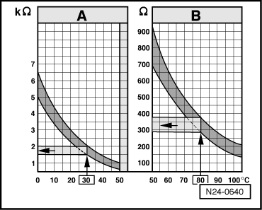
→ Specification see diagram

The diagram is divided into two temperature ranges:

  •      A -     From 0...50 °C
  •      B -     From 50...105 °C

Examples:

  • ◆ 30 °C is in range A and corresponds to a resistance of 1.5...2.0 kω
  • ◆ 80 °C is in range B and corresponds to a resistance of 275...375 ω

If the specification is not attained:

  • ‒ Renew coolant temperature sender -2- => Page 24-9 , item 20 .

If specification attained:

 
N24-0137
  • ‒ → Connect test box V.A.G 1598/18 to control unit wiring loom.
  • ‒ Check wiring between test box and 4 pin connector for open circuit according to current flow diagram.
         Contact 1+ socket 17
         Contact 3+ socket 42
         Wire resistance: max. 1.5 ω
  • ‒ Additionally check wires for short to one another, to vehicle earth and to battery positive.
         Specification: ∞ω

If no wiring fault is detected:

  • ‒ Renew engine control unit
    => Page 24-11 , item 28

Additional check when fault is stored as "Sporadic fault /SP":

Test conditions

  • ● Engine must be cold.

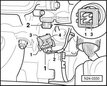
Functional check of sender

  • ‒ Connect fault reader V.A.G 1551 (V.A.G 1552). Start engine and select "Address word" 01 of engine control unit. When doing this the engine must be running at idling speed.
    (Connecting fault reader and selecting engine control unit => Page 01-4 .)
 
→ Indicated on display:
Rapid data transfer     HELP
Select function XX
  • ‒ Press keys 0 and 8 for the function "Read measured value block" and confirm entry with Q key.
 
→ Indicated on display:
Read measured value block     HELP
Input display group number XXX
  • ‒ Press keys 0, 0 and 1 for "Display group number 1" and confirm entry with Q key.
 
→ Indicated on display:
(1...4 = Display zones)
Read measured value block     1     ⇒
     1     2     3     4
  • ‒ Observe coolant temperature value in display zone 2, whilst engine is running. The temperature figure must
         increase uniformly and without interruption.

Notes:

  • ◆ If the display on fault reader jumps by 2...5 °C, it is a control unit fault and not caused by a defective sender.
  • ◆ If irregular engine running occurs in certain temperature ranges and the temperature figure does not increase without interruption, the temperature signal is temporarily interrupted and the sender must be renewed.
  • ‒ Press ⇒key.
  • ‒ Press keys 0 and 6 for the function "End output" and confirm entry with the Q key.

Checking intake air temperature sender > < Testing speed signal