volkswagen Workshop Repair Guides

Volkswagen Workshop Service and Repair Manuals

Checking intake air system for leaks (outside air) > < Checking fuel pressure regulator and holding pressure
Motronic injection and ignition system (4-Cyl. engine)
Motronic injection and ignition system
Checking injectors

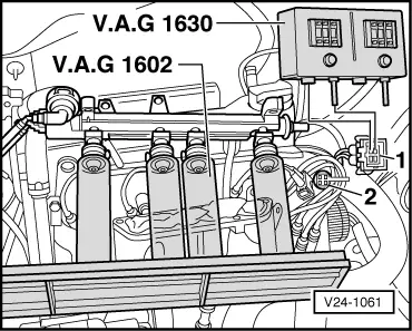
Special tools, testers and auxiliary items

  • ◆ Fault reader V.A.G 1551 with cable V.A.G 1551/3
  • ◆ Adapter set V.A.G 1594
  • ◆ Diode test lamp V.A.G 1527
  • ◆ Measuring unit V.A.G 1602
  • ◆ Digital potentiometer V.A.G 1630

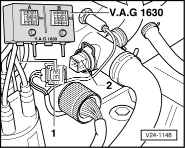
Checking resistance and voltage supply

Test conditions

  • ● Fault on injector recognized by self-diagnosis.

Test sequence

  • ‒ Remove intake manifold upper part , Item 6
  • ‒ Carry out electrical check, test steps 13...16 => Page 01-40

If electrical check specifications are attained:

  • ‒ Connect fault reader V.A.G 1551 and select engine electronics control unit (address word 01); selection is carried out with ignition switched on => Page 01-3 .
 
→ Indicated on display:
Rapid data transmission     HELP
Select function XX
  • ‒ Input 03 for "Final control diagnosis" function.
 
→ Indicated on display:
Rapid data transmission     Q
03 Final control diagnosis

Note:

If something different is indicated on the display:

=> Fault reader operating instructions

  • ‒ Check voltage supply of injectors. To do this, connect diode test lamp V.A.G 1527 with aux. cables from V.A.G 1594 first to No. 1 cylinder injector connector.
         The LED must light up.

Activate Cyl. 1 injector (N30):

  • ‒ Confirm input with Q button.
 
→ Indicated on display:
Final control diagnosis     ⇒
Injector cylinder 1 -N30
  • ‒ Open throttle valve fully and close again.
         The LED must flash.

The LED flashes:

  • ‒ Renew defective injector => Page 24-16 , Item 5

The LED does not flash:

  • ‒ Renew Motronic control unit (J220) => Page 24-8 , Item 12 .

To activate injectors, Cyls. 2...4 in each case:

  • ‒ Open throttle valve fully again and close.

If the electrical check specifications are not attained:

  • ‒ Pull 2 pin connector off all injectors.
  • ‒ Check resistance of each injector individually at contact using multimeter V.A.G 1526 and auxiliary cables from V.A.G 1594.
         Specification: 14...21.5 ω

If the specifications are not attained:

  • ‒ Renew defective injector => Page 24-16 , Item 5

If the specifications are attained:

  • ‒ Locate open circuit according to current flow diagram and rectify.

Checking spray pattern and for leaks

Test conditions

  • ● Engine speed sender OK.

Test sequence

  • ‒ Pull plug off ignition transformer.
  • ‒ Remove fuel manifold complete with injectors => Page 24-16 , Item 8 .
 
V24-1061
  • ‒ → Place injectors in the measuring unit V.A.G 1602.
  • ‒ Reconnect connectors to all injectors.
 
V24-1148
  • ‒ → Pull 4 pin connector -1- off coolant temperature sender (G62) -2-.
  • ‒ Set digital potentiometer V.A.G 1630 -side A- to 15 kωand using aux. cables from V.A.G 1594 connect contacts 1 and 3 of separated connector.
  • ‒ Operate starter. The injectors must spray uniformly.
  • ‒ Switch off ignition and check injectors for leaks. No more than
         2 drops/min
    may leak from each injector.

Note:

When installing the injectors ensure that the O-rings are not/will not be damaged. To facilitate installation, moisten O-rings slightly with oil.

  • ‒ Interrogate and erase fault memory, eliminate faults if necessary => Page 01-5 . The fault "Coolant temperature sender -G62" induced by the test will be erased.

Checking intake air system for leaks (outside air) > < Checking fuel pressure regulator and holding pressure