volkswagen Workshop Repair Guides

Volkswagen Workshop Service and Repair Manuals

Checking engine operation > < Checking idling stabilization
Motronic injection and ignition system (4-Cyl. engine)
Motronic injection and ignition system
Checking Lambda probe and Lambda control

Special tools, testers and auxiliary items

  • ◆ Fault reader V.A.G 1551 with cable V.A.G 1551/3
  • ◆ Adapter set V.A.G 1594

Test conditions

  • ● Idling check OK.
  • ● Exhaust system between catalyst and cylinder head free of leaks
  • ● Lambda probe heating voltage supply OK.

Test sequence

  • ‒ Start engine and run at idling speed.
  • ‒ Connect fault reader V.A.G 1551 and select engine electronics control unit (address word 01); selection is carried out with engine idling .
 
→ Indicated on display:
Rapid data transmission     HELP
Select function XX
  • ‒ Input 08 for "Read measuring value block" function and confirm with Q.
 
→ Indicated on display:
Reading measuring value block     HELP
Input display group number XX
  • ‒ Input 01 for display group 01 and confirm with Q.
 
→ Indicated on display:
(1...4 = Display zones)
Read measuring value block 1     ⇒
     1     2     3     4

Note:

If something different is indicated on the display:

=> Fault reader operating instructions

Do not continue with check until engine temperature exceeds 80 °C (display field 2).

  • ‒ Briefly increase engine speed (rev. up accelerator) and then allow engine to run at idling speed for 2 minutes.
  • ‒ Read Lambda factor in display zone 3.
         Specification: Display fluctuates around 1

Note:

If 1.29 is displayed there is a short circuit to earth in Lambda probe or wiring to control unit.

  • ‒ Press ⇒ button.
  • ‒ Input 06 for "End output" and confirm with Q.

If figures in display zone 3 do not fluctuate:

  • ‒ Repeat check after giving a burst on the throttle.

If after a throttle burst the display shoes a constant Lambda factor of 1.00:

  • ‒ Press ⇒ button.
  • ‒ Input 05 for "Erase fault memory" function and confirm with Q.
  • ‒ Press ⇒ button.
  • ‒ Input 08 for "Read measuring value block" function and confirm with Q.
 
→ Indicated on display:
Reading measuring value block     HELP
Input display group number XX
  • ‒ Input 01 for display group 01 and confirm with Q.
 
→ Indicated on display:
(1...4 = Display zones)
Read measuring value block 1     ⇒
     1     2     3     4
 
N24-0159
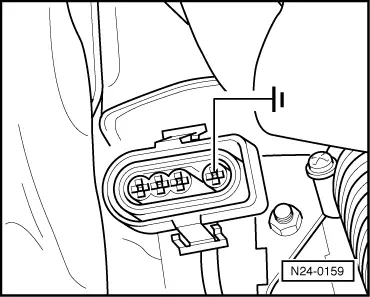
  • ‒ → Separate Lambda probe connector. Connect auxiliary cable from V.A.G 1594 to chamber 4 (wire to control unit -J220) and hold to an earth point. The figure in display zone 3 must
         rise

If the figure rises:

  • ‒ Renew Lambda probe (G39).

If the figure does not rise:

  • ‒ Carry out electrical check test step 20 => Page 01-40 .
  • ‒ Press ⇒ button.
  • ‒ Input 05 for "Erase fault memory" function and confirm with Q.
  • ‒ Press ⇒ button.
  • ‒ Input 06 for "End output" and confirm with Q.

Checking engine operation > < Checking idling stabilization