volkswagen Workshop Repair Guides

Volkswagen Workshop Service and Repair Manuals

READINESS code > < Final control diagnosis
Motronic injection and ignition system (4-cyl. engine)
Final control diagnosis
Performing final control diagnosis

The final control diagnosis activates the following components in the stated sequence:

  •      1 -     Injector No. 1 Cyl. (N30)
  •      2 -     Injector No. 2 Cyl. (N31)
  •      3 -     Injector No. 3 Cyl. (N32)
  •      4 -     Injector No. 4 Cyl. (N33)
  •      5 -     Solenoid valve 1 for activated charcoal filter (N80)
  •      6 -     Secondary air inlet valve (N112)
  •      7 -     Relay for secondary air pump (J299)

Special tools, workshop equipment, testers, measuring instruments and auxiliary items required

  • ◆ Fault reader V.A.G 1551 or vehicle system tester V.A.G 1552 with cable V.A.G 1551/3
  • ◆ Test box V.A.G 1598/22
  • ◆ Hand multimeter V.A.G 1526 or multimeter V.A.G 1715
  • ◆ Diode test lamp V.A.G 1527
  • ◆ Adapter set V.A.G 1594
  • ◆ Current flow diagram

Test conditions

  • ● The fuses 130 (on secondary air pump relay) and 18 must be OK.

Notes:

  • ◆ The final control diagnosis can only be carried out if the engine is stationary and ignition switched on.
  • ◆ The final control diagnosis will be aborted if the engine is started or a rotational impulse is recognised.
  • ◆ During the final control diagnosis the individual final controls will be activated until advancing to the next final control by pressing the ⇒ button.
  • ◆ The final controls are checked acoustically or by touching.
  • ◆ If it is necessary to repeat the final control diagnosis, without first running the engine briefly, switch the ignition off for approx. 2 seconds.
  • ◆ The electric fuel pump will run during the complete final control diagnosis.
  • ◆ The final control diagnosis will be aborted after 10 minutes.

Work sequence

  • ‒ Connect the fault reader V.A.G 1551 (V.A.G 1552). Then switch ignition on and select engine control unit with the "Address word" 01.
    (Connecting fault reader and selecting engine control unit .)
 
→ Indicated on display:
Rapid data transfer     HELP
Select function XX
  • ‒ Operate fault reader taking into account the information on the display:
  • ‒ Press keys 0 and 3 for the function "Final control diagnosis".
 
→ Indicated on display:
Rapid data transfer     Q
03 Final control diagnosis

Activate injectors (N30...N33):

  • ‒ Confirm input with Q key.
 
→ Indicated on display:
Final control diagnosis     ⇒
Injector cylinder 1 -N30

Note:

The fuel pump must run and the flow noise must be distinctly audible at the fuel pressure regulator. If the fuel pump does not run, check activation.

=> Repair group 20; Removing and installing parts of the fuel system; Checking fuel pump

  • ‒ Open the throttle valve. As soon as the idling switch opens, the number 1 Cyl. injector will click 5 times.
  • ‒ Press the ⇒key each time to advance to the next injector (advancing is also possible without testing each individual injector).
  • ‒ All injectors can be checked one after the other in this way.

If one of the injectors is not activated (does not click):

  • ‒ Checking injectors => Page 24-69 .

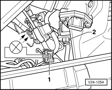
Activating activated charcoal filter solenoid valve 1 (N80):

  • ‒ Press ⇒key.
 
→ Indicated on display:
Final control diagnosis     ⇒
Activ. charcoal filter solenoid valve 1     -N80
  • The activated charcoal filter solenoid valve 1 must click until the next final control is activated by pressing ⇒key.

If the solenoid valve does not click:

 
V24-1054
  • ‒ → Pull connector -1- off solenoid valve -2- and connect diode test lamp V.A.G 1527 with aux. cables from V.A.G 1594 to disconnected connector.
         The LED must flash

LED flashes:

  • ‒ Proceed with final control diagnosis until completed.
  • ‒ Switch off ignition.
  • ‒ Renew solenoid valve.

=> Repair group 20; Removing and installing parts of fuel supply system; Servicing parts of activated charcoal filter system

LED does not flash:

  • ‒ Proceed with final control diagnosis until completed.
 
N24-1014
  • ‒ Switch off ignition.
  • ‒ → Connect test box V.A.G 1598/22 to control unit wiring harness.
  • ‒ Check wire between test box socket 15+2 pin connector contact 2 for open circuit using current flow diagram.
         Wire resistance: max. 1.5 ω
  • ‒ Additionally check wire for short to battery positive and earth.
         Specification: ∞ω
  • ‒ Check wire between 2 pin connector contact 1 and fuel pump relay (J17) for open circuit using current flow diagram.
         Wire resistance: max. 1.5 ω

If no wiring fault is detected:

  • ‒ Renew engine control unit => Page 24-120 .

Activating secondary air inlet valve (N112):

  • ‒ Press ⇒key.

Note:

On vehicles 05.00 ▸the secondary air inlet valve has been discontinued, but still exists in the test sequence for the final control diagnosis. Ignore the display on these vehicles and press ⇒ key again.

 
→ Indicated on display:
Final control diagnosis     ⇒
Secondary air inlet valve -N112
  • The secondary air inlet valve must run until the next control element is activated by pressing the ⇒ key.

If the valve does not click:

 
N24-1016
  • ‒ → Pull connector -1- off solenoid valve -2- and connect diode test lamp V.A.G 1527 with aux. cables from V.A.G 1594 to disconnected connector.
         The LED must flash

LED flashes:

  • ‒ Proceed with final control diagnosis until completed.
  • ‒ Switch off ignition.
  • ‒ Replace secondary air inlet valve:

=> Repair group 26; Secondary air system; Removing and installing parts of the secondary air system

LED does not flash:

  • ‒ Proceed with final control diagnosis until completed.
  • ‒ Switch off ignition.
 
N24-1014
  • ‒ → Connect test box V.A.G 1598/22 to control unit wiring harness.
  • ‒ Check wire for open circuit between test box socket 33 and 2 pin connector contact 2 using current flow diagram.
         Wire resistance: max. 1.5 ω
  • ‒ Additionally check wire for short to battery positive and earth.
         Specification: ∞ω
  • ‒ Check wire between 2 pin connector contact 1 and fuel pump relay (J17) for open circuit using current flow diagram.
         Wire resistance: max. 1.5 ω

If no wiring fault is detected:

  • ‒ Renew engine control unit => Page 24-120 .

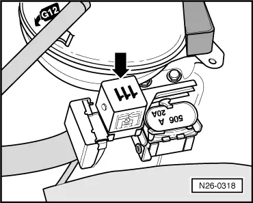
Activating secondary air pump relay (J299):

  • ‒ Press ⇒key.
 
→ Indicated on display:
Final control diagnosis     ⇒
Secondary air pump relay -J299
  • The secondary air pump relay (J299) activates the secondary air pump motor, and this must run at intervals until the next control element is activated by pressing the ⇒ key.

If the secondary air pump motor (V101) does not run at intervals:

 
N24-1015
  • ‒ → Pull 2 pin connector -1- off secondary air pump motor -2- and connect diode test lamp V.A.G 1527 with aux. cables from V.A.G 1594 to disconnected connector.
         The LED must flash

LED flashes:

  • ‒ Proceed with final control diagnosis until completed.
  • ‒ Switch off ignition.
  • ‒ Renew secondary air pump motor (V101):

=> Repair group 26; Secondary air system; Removing and installing parts of secondary air system

If the LED does not flash but the secondary air pump relay clicks:

  • ‒ Proceed with final control diagnosis until completed.
  • ‒ Switch off ignition.
  • ‒ Check the wire between secondary air pump motor (V101) and contact 1 and body earth for open circuit.

If no wiring fault is detected:

 
N26-0318
  • ‒ → Pull secondary air pump relay -arrow- off relay plate.

Notes:

  • ◆ If tools are necessary to pull relays or control units out of the relay plate, first disconnect battery earth strap.
  • ◆ Before disconnecting battery earth strap obtain code for radios with anti-theft coding.
  • ‒ Using current flow diagram check wire between secondary air pump motor (V101) contact 2 and contact 8 on relay plate for open circuit.

If no wiring fault is detected:

  • ‒ Using current flow diagram check the voltage supply (terminal 30) for secondary air pump relay (J299).

If voltage supply is OK:

  • ‒ Renew secondary air pump relay (J299).

If the LED does not flash and the secondary air pump relay does not click:

  • ‒ Proceed with final control diagnosis until completed.
  • ‒ Switch off ignition.
 
N26-0318
  • ‒ → Pull secondary air pump relay -arrow- off relay plate.

Notes:

  • ◆ If tools are necessary to pull relays or control units out of the relay plate, first disconnect battery earth strap.
  • ◆ Before disconnecting battery earth strap obtain code for radios with anti-theft coding.
  • ‒ Initiate final control diagnosis and activate secondary air pump valve (J299).
  • ‒ Using adapter cables from V.A.G 1594 connect the diode test lamp V.A.G 1527 to contacts 4 and 6 on the relay plate.
         The LED must flash

LED flashes:

  • ‒ Renew secondary air pump relay (J299).

LED does not flash:

  • ‒ Using adapter cables from V.A.G 1594 connect the diode test lamp V.A.G 1527 to contact 6 of relay plate and body earth.
         The LED must light-up

LED does not light-up:

 
N24-1014
  • ‒ Check wiring for open circuit between relay plate contact 6 and fuel pump relay using current flow diagram.

LED lights up:

  • ‒ Proceed with final control diagnosis until completed.
  • ‒ Switch off ignition.
  • ‒ → Connect test box V.A.G 1598/22 to control unit wiring harness.
  • ‒ Check the wire between test box socket 30 and contact 4 on the relay plate for open circuit using current flow diagram.
         Wire resistance: Max. 1.5 ω

If no wiring fault is detected:

  • ‒ Renew engine control unit => Page 24-120 .
  • ‒ Press ⇒key.
 
→ Indicated on display:
Rapid data transfer     HELP
Select function XX
  • ‒ Press keys 0 and 6 for the function "End output" and confirm entry with the Q key.
  • ‒ Switch off ignition.

Note:

After completion of the final control diagnosis switch off ignition. If the ignition is not switched off before attempting to start, the engine will not start, as the injectors and the ignition transformer will not be activated.

READINESS code > < Final control diagnosis