|
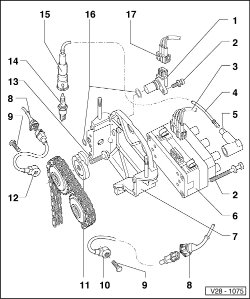
Motronic injection and ignition system with distributor-less ignition
General notes on ignition system
-
◆ Only the components which specifically relate to the ignition system are dealt with here. For the other components of the injection and ignition system => Repair group 24.
-
◆ Disconnecting and connecting the battery must only be done with the ignition switched off, otherwise the engine control unit could be damaged.
-
◆ The engine control unit is equipped with self diagnosis.
-
◆ Components marked with * are checked via the self diagnosis.
, interrogating fault memory
-
◆ For trouble-free operation of the electrical components a voltage of at least 11.5 V is necessary.
-
◆ During some checks it is possible that the control unit will recognise and store a fault. Therefore after completing all checks and repairs the fault memory must be interrogated and if necessary erased.
=> Page 01-13
, interrogating fault memory
-
◆ If the engine starts, runs for a short period and then stops, after fault finding, repairs or component tests, then the fault may lie with the immobilizer which is blocking the engine control unit. The fault memory must be interrogated and if necessary the control unit matched => Page 24-122
.
Safety precautions => Page 28-6
Test data, spark plugs => Page 28-7
|