
Golf Mk3
| → Indicated on display: |
|
||
|
| → Indicated on display: |
|
||
|
| →
Indicated on display: (1...4 = Display zones) |
|
||
|
| → Indicated on display: |
|
||
|
|
→
Indicated on display: (1...4 = Display zones) |
|
||
If the specifications are not attained or there is a fault in fault memory relating to the air mass meter, |
 |
|
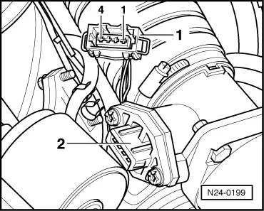
Testing power supply to air mass meter Vehicles with 4 pin connector
|
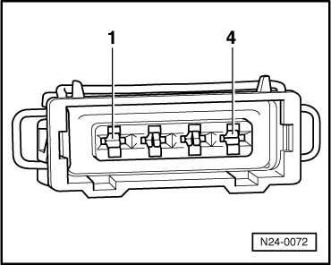 |
|
If no voltage was present:
=> Current flow diagrams, Electrical fault finding and Fitting locations binder Vehicles with 6 pin connector |
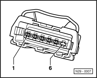 |
|
Note: Pin 6 vacant.
If no voltage was present:
=> Current flow diagrams, Electrical fault finding and Fitting locations binder Continued for all vehicles Testing signal wiring for air mass meter |
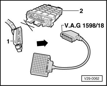 |
|
Vehicles with 4 pin connector
Vehicles with 6 pin connector
Continued for all vehicles
If no wiring fault is detected:
|