volkswagen Workshop Repair Guides

Volkswagen Workshop Service and Repair Manuals

Checking engine operating mode > < Idling check
Motronic injection and ignition system (6-Cyl. engine)
Checking functions
Checking Lambda control

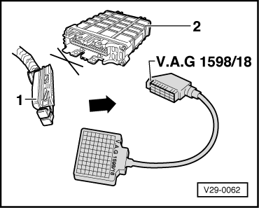
Special tools, testers, measuring instruments and auxiliary items required

  • ◆ Fault reader V.A.G 1551 or vehicle system tester V.A.G 1552 with cable V.A.G 1551/3
  • ◆ Test box V.A.G 1598/18
  • ◆ Hand multimeter V.A.G 1526 or multimeter V.A.G 1715
  • ◆ Adapter set V.A.G 1594
  • ◆ Current flow diagram

Check conditions

  • ● The engine control unit must be matched to the throttle valve control part
  • ● Coolant temperature at least 85 °C.
  • ● Exhaust system between catalyst and cylinder head must be free of leaks

Functional check

  • ‒ Connect fault reader V.A.G 1551 (V.A.G 1552). Start engine and select "Address word" 01 of engine control unit. When doing this the engine must be running at idling speed.
    (Connecting fault reader and selecting engine control unit => Page 01-5 .)
 
→ Indicated on display:
Rapid data transfer     HELP
Select function XX
  • ‒ Press keys 0 and 8 for the function "Read measured value block" and confirm entry with Q key.
 
→ Indicated on display:
Read measured value block     HELP
Input display group number XXX
  • ‒ Press keys 0, 0 and 1 for "Display group number 1" and confirm entry with Q key.
 
→ Indicated on display:
(1...4 = Display zones)
Read measured value block     1     ⇒
     1     2     3     4
  • ‒ Check whether the coolant temperature is above 85 °C in display zone 2.
  • ‒ Change to display group 7 as follows:
  • ‒ Press the ⇒key.
 
→ Indicated on display:
Read measured value block     HELP
Input display group number XXX
  • ‒ Press keys 0, 0 and 7 for "Display group number 7" and confirm entry with Q key.
 
→ Indicated on display:
(1...4 = Display zones)
Read measured value block 7     ⇒
     1     2     3     4
  • ‒ Note Lambda probe voltage in display zone 4. The voltage must
         fluctuate at least 30 times per minute
    in range of
         0... 1.0 V.
  • ‒ Press ⇒key.
  • ‒ Press keys 0 and 6 for the function "End output" and confirm entry with the Q key.
  • If the Lambda regulation does not fluctuate as stated:

    • ‒ Carry out road test and burn Lambda probes clean and repeat check.

    If the specifications are not obtained again:

    • ‒ Check Lambda probe heating => Page 24-27 .

    If the voltage change is slower, determine cause of fault. => Page 24-100 .

    If the displayed figure remains constant:

    • ‒ Continue check according to following table.

    Display

    Cause

    Continuation of check

    Between 0.400...
    0.500 V

    Open circuit

    => Page 24-102 checking Lambda probe wiring

    1.105 V

    Short to positive

    0.000 V

    Short to earth

    Possible causes of fault if probe control frequency is too slow:

    • ◆ The slots or holes in probe body are blocked
    • ◆ The probe vent hole in area of connecting wire is blocked
    • ◆ The probe has been overheated (glazed)
    • ◆ The probe has been damaged by leaded fuel
     
    N24-0279

    Checking basic voltage

    • ‒ → Separate 4 pin connector (black) to Lambda probe before catalyst (G39).
     
    N24-0220
    • ‒ → Connect multimeter with aux. cables from V.A.G 1594 to measure voltage at contacts 3+4 (connector to engine control unit).
    • ‒ Switch on ignition and measure basic voltage.
           Specification: 0.40...0.50 V
    • ‒ Switch off ignition.

    If the specification is not obtained:

    • ‒ Check Lambda probe wiring
      => Page 24-102

    If the specification is attained:

    • ‒ Replace Lambda probe (G39).

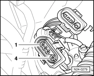
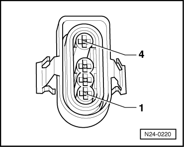
    Checking Lambda probe wiring

     
    V29-0062
    • ‒ → Connect test box V.A.G 1598/18 to control unit wiring loom.
     
    N24-0279
    • ‒ → Separate 4 pin connector (black) to Lambda probe before catalyst (G39).
     
    N24-0220
    • ‒ → Check wiring between test box and 4 pin connector (to control unit) for open circuit according to current flow diagram.
           Contact 3+socket 42
           Contact 4+socket 20
           Wire resistance: Max. 1.5 ω
    • ‒ Check wiring at connector contacts 3+4 for short circuit to contacts 1+2 using current flow diagram.
           Specification: ∞ω

    If no wiring fault is detected:

    • ‒ Replace Lambda probe (G39).

    Checking engine operating mode > < Idling check