volkswagen Workshop Repair Guides

Volkswagen Workshop Service and Repair Manuals

Checking control unit voltage supply > < Checking engine speed sender
Motronic injection and ignition system from 08.95
Motronic injection and ignition system
Checking speed signal

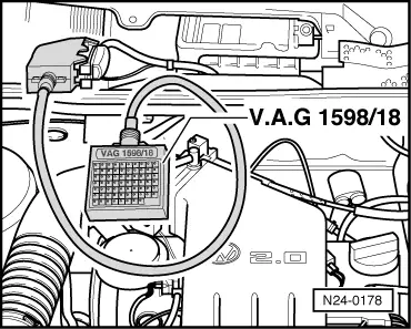
Special tools, testers and auxiliary items

  • ◆ Fault reader V.A.G 1551 or vehicle system tester V.A.G 1552 with cable V.A.G 1551/3
  • ◆ Hand multimeter V.A.G 1526 or multimeter V.A.G 1715
  • ◆ Adapter set V.A.G 1594
  • ◆ Current flow diagram

Test conditions

  • ● Speedometer OK., checking:

=> Repair group 90, Electrical system

Note:

To check the speed signal the vehicle must be driven. To do this a second person is necessary.

Test sequence

  • ‒ Connect fault reader V.A.G 1551 (V.A.G 1552) and select engine electronics control unit with the "Address word" 01. When doing this the engine must be running at idling speed.
    (Connecting fault reader and selecting engine electronics control unit .)
 
→ Indicated on display:
Rapid data transfer     HELP
Select function XX
  • ‒ Press keys 0 and 8 for the function "Read measured value block" and confirm entry with Q key.
 
→ Indicated on display:
Read measured value block     HELP
Input display group number XXX
  • ‒ Press keys 0, 0 and 5 for "Display group number 5" and confirm entry with Q key.
 
→ Indicated on display:
(1...4 = Display zones)
Read measured value block 5     ⇒
     1     2     3     4
  • ‒ Carry out test drive and observe display in display zone 3 (2nd person necessary).

Display zones

1

2

3

4

Display group 5: General engine data

Display

xxx rpm

xx.xx ms

xxx km/h

Idling

Indicated

Engine speed

Engine load

Driving speed

Operating modes

Working range

800...6000 rpm

0.00...25.00 ms

---

---

Specification

---

---

Approx. driving speed

---

---

---

If no driving speed is displayed , continued

  • ‒ Press ⇒key.
  • ‒ Press keys 0 and 6 for the "End data transfer" function and confirm input with the Q key.
  • ‒ Switch off ignition.

Continuation

 
N24-0180

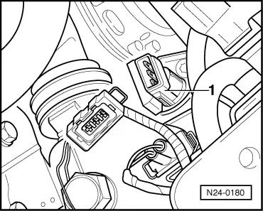
If no speed is indicated:

  • ‒ → Pull 3 pin connector off road speed sender -1-.
  • ‒ Switch ignition on..
 
N24-0181
  • ‒ → Connect multimeter using aux. cables from V.A.G 1594 to measure voltage at contacts 1+3 of connector.
         Specification: 9...14.5 V
  • ‒ Switch off ignition.
  • ‒ Reconnect connector

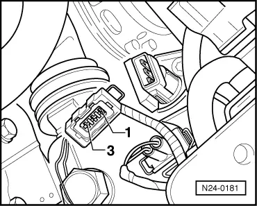
If no voltage was present:

  • ‒ Check wiring according to current flow diagram.

If voltage was 9...14.5 V:

 
N24-0178
  • ‒ → Connect test box V.A.G 1598/18 to control unit wiring loom -arrow-.
  • ‒ Check wiring between central electrics and socket 65 for open circuit according to current flow diagram.
         Wire resistance: Max. 1.5 ω
  • ‒ Connect multimeter using aux. cables from V.A.G 1594 to measure voltage at sockets 56+65.
  • ‒ Switch ignition on.
  • ‒ Raise left front wheel or push vehicle. The voltage figure must fluctuate between
         0...at least 4 V.

If no wiring fault is detected and voltage was present between contacts 1+3:

  • ‒ Replace speedometer sender (G22).
  • ‒ Read-out the readiness code=> Page 01-35 .

Checking control unit voltage supply > < Checking engine speed sender