
Golf Mk3
 |
|
|
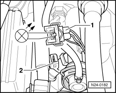
Engine codes ADY, AGG, AKR
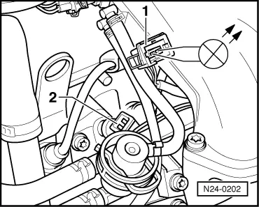
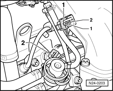
Engine codes AFT, AKS
|
 |
|
Continued for all engine codes
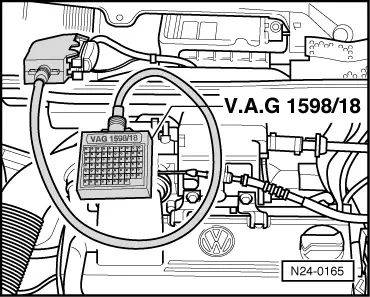
The LED does not flicker: |
 |
|
|
 |
|
Checking resistance of injectors |
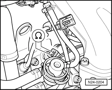 |
|
If the specification is not attained, replace injector(s) as necessary. Checking spray pattern and for leaks Warning!
The fuel system is pressurized! Before loosening hose connections or opening the test connection, wrap a cloth around the connection. Then release pressure by carefully pulling off the hose/sealing cap. Special tools, testers and auxiliary items
Test sequence Engine codes ADY, AGG, AKR |
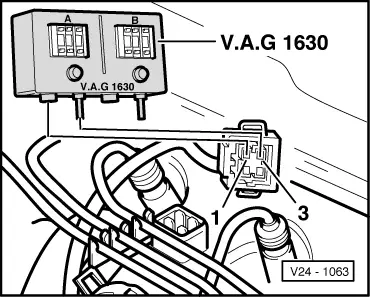 |
|
Engine codes AFT, AKS |
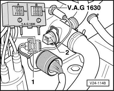 |
|
Continued for all engine codes |
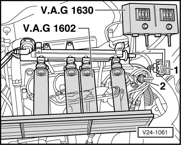 |
|
Note: When installing the injectors ensure that the O rings are not damaged. |