
Golf Mk3
| Removing and installing subframe, anti-roll bar and suspension link (basic running gear) |
 Note
Note| t | If a vehicle has to be moved after the drive shaft has been removed, first install an outer joint instead of the drive shaft and tighten to 50 Nm because otherwise the wheel bearing will be damaged. |
| t | It is not permitted to weld or straighten suspension parts which bear loads or locate the wheels. |
| t | Always renew self-locking nuts. |
| t | Always renew corroded nuts and bolts. |

| 1 - | 35 Nm |
| 2 - | Swivel joint |
| q | Checking → Chapter |
| q | Check rubber bellows for damage, install a new swivel joint if necessary |
| q | Mark installation position; if suspension link is renewed, set to centre of elongated hole and check toe setting. |
| q | Elongated holes are not used to set camber! |
| 3 - | Plate with nuts |
| 4 - | Suspension link |
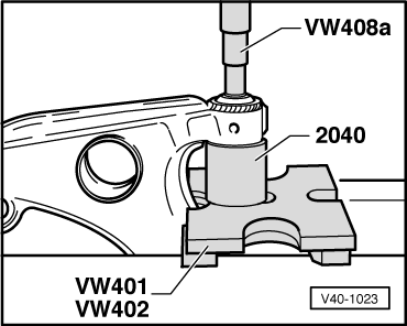
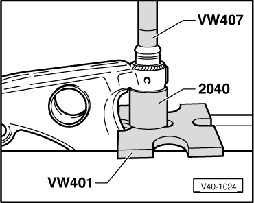
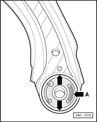
| 5 - | Rear wishbone bush |
| q | Installation position → Fig.. |
| q | Pressing out and in → Fig.. |
| q | Modification → Chapter |
| 6 - | Connecting link mounting |
| q | Conical side to suspension link. |
| 7 - | Coupling rod |
| 8 - | Rubber bush |
| q | Before pressing in, coat with assembly paste -G 052 109 A2-. |
| 9 - | 65 Nm |
| 10 - | Rubber bush |
| 11 - | Anti-roll bar |
| q | Allocation → Chapter. |
| 12 - | 25 Nm |
| 13 - | Clamp |
| 14 - | Vibration damper |
| 15 - | 25 Nm |
| 16 - | Subframe |
| q | Removing and installing when assemblies are installed: support assemblies → Fig.. |
| q | Remove subframe with suspension links (but without steering box) out downwards using engine and gearbox jack -V.A.G 1383-. Check position of steering wheel after installing. |
| q | Aligning engine/gearbox assembly → Rep. Gr.10. |
| 17 - | Hexagon bolt M12 x 1.5 x 82 |
| q | 50 Nm and turn 90° further. |
| 18 - | Hexagon bolt M12 x 1.5 x 65 |
| q | 70 Nm and turn 90° further. |
| 19 - | Hexagon bolt M12 x 1.5 x 78 |
| q | 70 Nm and turn 90° further. |
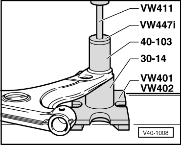
| 20 - | Front wishbone bush |
| q | Pressing out → Fig.. |
| q | Pressing in → Fig.. |
| 21 - | Washer |
| q | Collar faces away from bush. |
| 22 - | 25 Nm |
| 23 - | Cap nut |
| q | Reworking in longitudinal member → Chapter. |
|
|
Note
|
|
|
|
|
|