volkswagen Workshop Repair Guides

Volkswagen Workshop Service and Repair Manuals

Checking outer constant velocity joint > < Removing and installing drive shafts on a vehicle with compressed splines in wheel hub
Running gear
Servicing drive shaft

Drive shafts on vehicles with plus running gear have shorter and finer splines on the outer joint. The wheel bearing is secured by a 12-point nut.

The splines of the outer joint and the hub are secured with locking fluid D 185 400 A2.

Removing and installing drive shaft on vehicles with plus running gear

Notes:

  • ◆ Quantity of grease for vehicles up to 48 kW: outer and inner 90 gramme G 6.3
  • ◆ Quantity of grease for vehicles with 55 kW and above:
  • ◆ Outer: 110 gramme G 6.3
  • ◆ Inner: 120 gramme G 6.3
  • ◆ Greasing outer joint: press half of the grease into the joint, and the other half evenly into the bellows.
  • ◆ Greasing inner joint: press half of the grease into the inner joint from both sides, the other half evenly into the bellows.
  • ◆ When renewing the bellows grease joint as required.
 
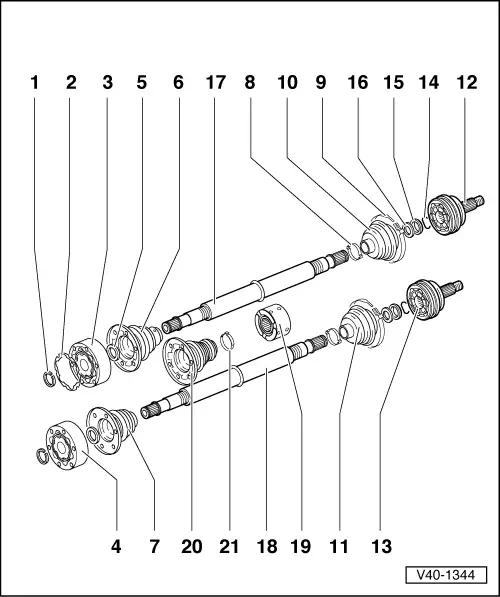
V40-1344
  • Circlip
    • ◆ Renew
    • ◆ Remove and install with
      VW 161 a
  • Gasket
    • ◆ Renew. Pull off protective foil and stick onto joint. Only on 100 mm ø constant velocity joints
    • Modification
    • ◆ From 08.93 also on constant velocity joint with 90 mmø
  • Inner constant velocity joint
    100 mm ø for vehicles with 55 kW output and above
    • ◆ Only renew complete
    • ◆ Pressing off => Fig.3
    • ◆ Pressing on => Fig.4
    • ◆ Greasing => Notes Page 40-68
    • ◆ Checking => Page 40-82
 
V40-1344
  • Inner constant velocity joint 94 mm øfor vehicles up to 48 kW output
    • ◆ Pressing off => Fig.3
    • ◆ Pressing on => Fig.4
    • ◆ Greasing => Notes Page 40-68
    • ◆ Checking => Page 40-82
  • Dished washer
    • ◆ Inner øsplined
    • ◆ Installation position: outer ø(concave side) contacts constant velocity joint
  • Bellows for 100 mm øconstant velocity joint
    • ◆ With vent hole
    • ◆ Check for tears and chafing
    • ◆ Installation position for left drive shaft => Fig.5
    • ◆ Installation position for right drive shaft => Fig.6
    • ◆ Coat inside of cap with D3
    • ◆ Drive off with drift
 
V40-1344
  • Bellows for 94 mm øconstant velocity joint
    • ◆ Check for tears and chafing
    • ◆ Drive off with drift
  • Clamp
    • ◆ Renew
    • ◆ Tensioning => Fig.7 and Fig.8
  • Hose clamp
    • ◆ Renew
    • ◆ Tensioning => Fig.7 and Fig.8
  • Bellows for 90 mm øconstant velocity joint
    • ◆ Check for tears and chafing
    • ◆ To balance pressure briefly ventilate bellows before tensioning the small clamp=>Fig. 7
 
V40-1344
  • Bellows for 81 mm øconstant velocity joint
    • ◆ Check for tears and chafing
    • ◆ To balance pressure briefly ventilate bellows before tensioning the small clamp =>Fig.7
  • Outer 90 mm ø constant velocity joint for vehicles with 55 kW output and above
    • ◆ Only renew complete
    • ◆ Removing =>Fig.2
    • ◆ Installing: drive onto shaft with plastic hammer until compressed circlip seats
    • ◆ Greasing => Notes Page 40-68
    • ◆ Checking => Page 40-80
 
V40-1344
  • Outer 81 mm ø constant velocity joint for vehicles up to 48 kW output
    • ◆ Only renew complete
    • ◆ Removing =>Fig.2
    • ◆ Installing: drive onto shaft with plastic hammer until compressed circlip seats
    • ◆ Greasing => Notes Page 40-68
    • ◆ Checking => Page 40-80
  • Circlip
    • ◆ Renew
    • ◆ Insert in shaft groove
  • Thrust washer
  • Dished washer
    • ◆ Outer ø (concave side) contacts thrust washer
 
V40-1344
  • Constant velocity joint for vehicles with 55 kW output and above
    • ◆ Constant velocity joint splines are 4 mm longer than vehicles with lesser outputs, measure from dished washer seat to circlip groove
  • Drive shaft for vehicles up to 48 kW output
  • Vibration damper
    • ◆ Installation position =>Fig.1
  • Bellows for 94 and 100 mm øconstant velocity joint
    • ◆ Installed: from 01.93
  • Hose clamp
    • ◆ Tensioning =>Fig. 9
 
V40-1081

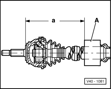
→ Fig.1    Vibration damper installation position

When installing vibration damper -A- note correct installation position. Ensure dimension "a" is maintained.

Dim. "a" mm

Engine

541 ± 1

1.8 ltr. - 55 kW


1.8 ltr. - 66 kW


1.9 ltr. - 48 kW


1.9 ltr. - 55 kW


2.0 ltr. - 85 kW


2.0 ltr. - 110 kW

525 ± 1

1.9 ltr. - 47 kW


1.9 ltr. - 66 kW

 
V40-0464

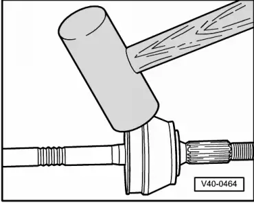
→ Fig.2    Removing outer constant velocity joint

  • ‒ Drive joint off drive shaft with a firm blow from an aluminium hammer.
 
V40-0859

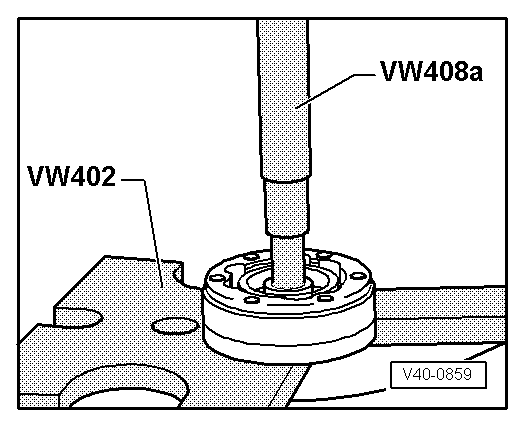
→ Fig.3     Pressing off inner constant velocity joint

Notes:

  • ◆ First drive bellows off with drift
  • ◆ Support ball hub
 
V40-0860

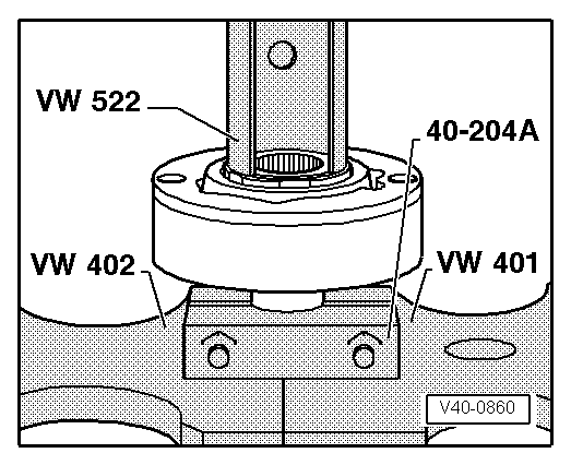
→ Fig.4    Pressing on inner constant velocity joint

  • ‒ Press on joint up to stop.
  • ‒ Insert circlip.

Note:

Chamfer on inner diameter of ball hub (splines) must face the contact shoulder on the drive shaft.

 
V40-0870

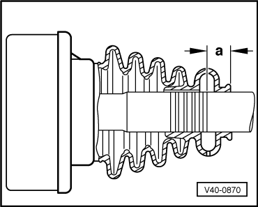
→ Fig.5    Installation position of left drive shaft joint bellows

Dimension a = 17 mm

Note:

Before assembling bellows on drive shaft mark position, dimension -a-, with for example paint or adhesive tape. Under no circumstances should paint surface be damaged.

 
V40-0871

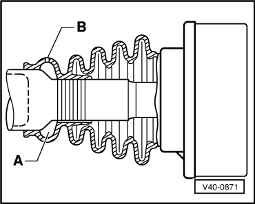
→ Fig.6    Installation position of right drive shaft joint bellows

The large diameter of vent chamber -A- must fit on the larger diameter.

  •     B -    Vent hole
 
V40-0837

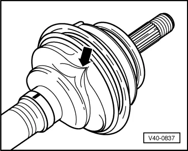
→ Fig.7    Ventilating joint bellows

Often the bellows is pushed in when installing on the joint body. This creates a vacuum inside the bellows which draws a fold in (arrow) whilst driving. Therefore after fitting, lift the bellows at small diameter end to equalize pressure.

 
V40-1076

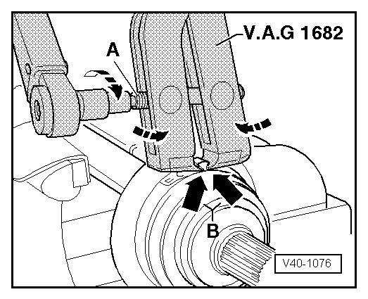
→ Fig.8    Tensioning outer joint hose clamp

  • ‒ Fit pliers V.A.G 1682 as shown in illustration. Thereby ensure that the jaws of the pliers seat in the corners (arrow B) of the hose clamp.
  • ‒ Tension hose clamp by turning the spindle with a torque wrench (do not cant pliers).

Notes:

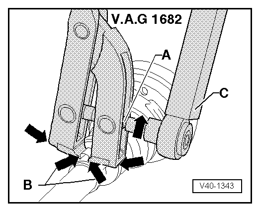
  • ◆ Due to the hard material of the joint bellows (compared to rubber) and, due to this the necessary stainless steel hose clamp, it is only possible to tension the hose clamp with pliers V.A.G 1682.
  • ◆ Tightening torque: 25 Nm.
  • ◆ Use torque wrench with 5...50 Nm range (e.g. V.A.G 1331).
 
V40-1343
  • ◆ Ensure the the spindle thread is not tight. If necessary lubricate with MOS 2 grease
  • ◆ If the thread is tight e.g. dirty, the required tensioning force for the hose clamp will not be achieved inspite of correct tightening torque settings.

→ Fig.9    Tensioning inner joint hose clamp (from 01.93)

Checking outer constant velocity joint > < Removing and installing drive shafts on a vehicle with compressed splines in wheel hub