volkswagen Workshop Repair Guides

Volkswagen Workshop Service and Repair Manuals

Removing and installing ball joint > < Servicing front suspension (Plus running gear)
Running gear
Servicing front suspension (Plus running gear)
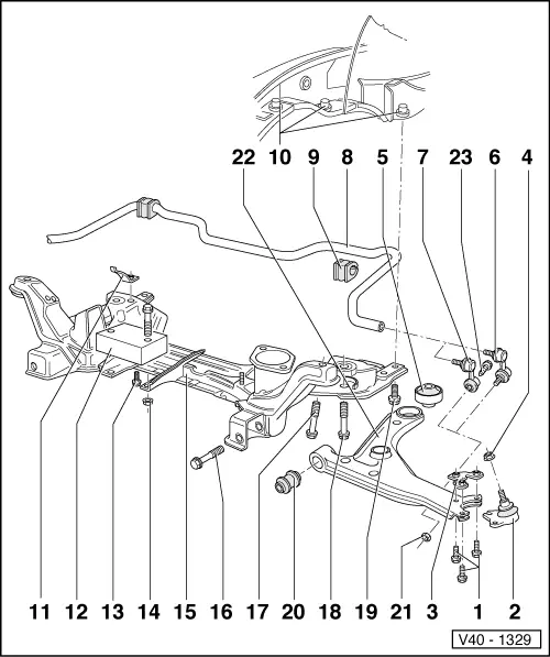
Removing and installing sub-frame, anti-roll bar and wishbone (Plus running gear)
 
V40-1329

Notes:

  • 35 Nm
  • Ball joint
    • ◆ Checking
    • ◆ Check rubber boot for damage and if necessary, renew ball joint
    • ◆ Removing and installing
      => Page 40-39
    • ◆ Mark installation position. If renewed set to centre of elongated hole and check track
  • Plate with nuts
  • Self-locking nut, 45 Nm
 
V40-1329
  • Rear wishbone mounting
    • ◆ Installation position => Fig.2
    • ◆ Pressing out and in => Fig.3
    • ◆ Modification => Page 40-9
  • Connecting link
    • ◆ Up to 04.92
  • Connecting link
    • ◆ From 04.92
  • Anti-roll bar
  • Rubber mounting
    • ◆ Allocation => Page 40-42
  • Cap nut
    • ◆ Reworking in side member => Page 40-12
  • Clamp
 
V40-1329
  • Vibration damper
    • ◆ Not installed on vehicles with VR 6 engine
  • 25 Nm
  • 25 Nm
  • Sub-frame
    • ◆ Removing and installing with assemblies fitted: supporting assemblies => Fig.4
    • ◆ Remove sub-frame from below with wishbone but without steering box using gearbox jack V.A.G 1383. After installing check position of steering wheel
    • ◆ Aligning engine/gearbox assembly

=> Repair group 10

 
V40-1329
  • Hexagon bolt
    M 12 x 1.5 x 82
    • ◆ 50 Nm and turn 90° further
  • Hexagon bolt
    M 12 x 1.5 x 65
    • ◆ 70 Nm and turn 90° further
  • Hexagon bolt
    M 12 x 1.5 x 78
    • ◆ 70 Nm and turn 90° further
  • 65 Nm
  • Front wishbone mounting
    • ◆ Pressing out and in => Fig.1
  • 25 Nm
  • Wishbone
    • ◆ Elongated holes are not for camber adjustment!
  • Hexagon bolt
 
V40-1312

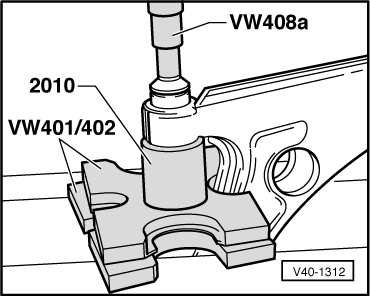
→ Fig.1    Pressing front wishbone mounting out and in

Note:

Before pressing in, coat with lubricant e.g. soft soap.

 
V40-1010

→ Fig.2    Rear wishbone mounting installation position

One of the embossed arrows points towards the recess in the wishbone and the kidney shaped opening (arrow A) in mounting faces towards centre of vehicle.

 
V40-1008

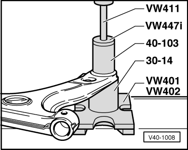
→ Fig.3    Pressing rear wishbone mounting out and in

 
V40-1305

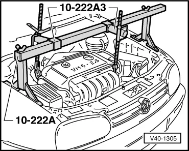
→ Fig.4    Support engine/gearbox assembly with 10-222 A and 10-222 A/3

Removing and installing ball joint > < Servicing front suspension (Plus running gear)