
Golf Mk4
 Note
Note
|

| 1 - | 100 Nm |
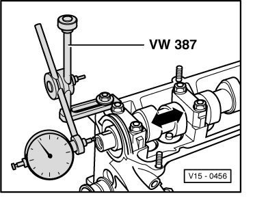
| q | Use counterhold tool -3415- to loosen and tighten. |
| 2 - | Camshaft toothed belt pulley |
| 3 - | Seal |
| q | Renew → Chapter. |
| 4 - | Woodruff key |
| q | Check for secure seating. |
| 5 - | 20 Nm |
| 6 - | Bearing cap |
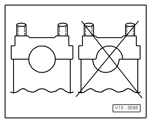
| q | Installation position → Fig.. |
| q | Installation sequence → Chapter, removing and installing camshaft. |
| q | Lightly coat contact surface of bearing cap 1 with sealant -AMV 174 004 01-. |
| 7 - | Camshaft |
| q | Checking axial clearance → Fig.. |
| q | Removing and installing → Chapter. |
| q | Check radial clearance with plastigage, wear limit: 0.1 mm. |
| q | Runout: max. 0.05 mm. |
| 8 - | Bucket tappet |
| q | Do not interchange. |
| q | With hydraulic valve clearance compensation. |
| q | Checking → Chapter. |
| q | Store with cam contact surface downwards. |
| q | Before installing check camshaft axial clearance → Fig.. |
| q | Oil contact surface. |
| 9 - | Cotters |
| 10 - | Upper valve spring plate |
| 11 - | Valve spring |
| q | Removing and installing: with cylinder head removed, use valve spring compressor -2037-; with cylinder head installed → Chapter |
| 12 - | Valve stem seal |
| q | Renew → Chapter. |
| 13 - | Valve guide |
| q | Checking → Chapter. |
| q | Renew → Chapter. |
| q | Service version with collar. |
| 14 - | Cylinder head |
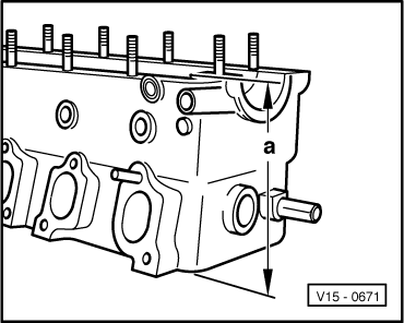
| q | Reworking sealing surface → Fig.. |
| q | Reworking valve seats → Chapter. |
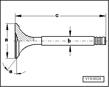
| 15 - | Valves |
| q | Do not rework, only lapping-in is permitted. |
| q | Valve dimensions → Fig. |
Note
|
|
|
|
|
|
|
|
Note
|
|
| Dimension | Inlet valve | Exhaust valve | |
| Ø a | mm | 39,5 ± 0,15 | 32,9 ± 0,15 |
| Ø b | mm | 6,98 ± 0,007 | 6,96 ± 0,007 |
| c | mm | 91,85 | 91,15 |
| α | ∠° | 45 | 45 |