
Golf Mk4
| Parts of cooling system - engine side |
 Note
Note| Coolant hose schematic diagram → Chapter |
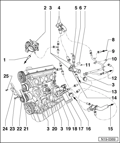
| 1 - | To top of expansion tank. |
| 2 - | Throttle valve positioner |
| q | Heated by coolant. |
| 3 - | O-ring |
| q | Renew if damaged. |
| 4 - | Connections on heat exchanger for heater. |
| 5 - | Connector |
| q | 4-pin |
| q | Gold-plated contacts for coolant temperature sender -G62-. |
| 6 - | Coolant temperature sender -G62- |
| q | For engine control unit. |
| q | With coolant temperature sender -G2-. |
| q | Gold-plated contacts for coolant temperature sender -G62-. |
| q | Before removing, relieve pressure in cooling system if necessary. |
| 7 - | Securing clip |
| q | Check for secure seating. |
| 8 - | From ATF radiator (automatic gearbox) or moulded hose to → Item |
| 9 - | 25 Nm |
| 10 - | Coolant pipe |
| 11 - | 10 Nm |
| 12 - | To bottom of expansion tank. |
| 13 - | From ATF radiator (automatic gearbox) or moulded hose to → Item |
| 14 - | Connection |
| 15 - | To top of radiator |
| 16 - | To bottom of radiator |
| 17 - | Oil cooler |
| q | Ensure clearance to adjacent components. |
| q | See note → Chapter. |
| 18 - | 15 Nm |
| 19 - | Connection |
| 20 - | Thermostat |
| q | Check: heat up thermostat in water bath. |
| q | Starts to open at approx. 86°C. |
| q | Opening stroke approx. 7 mm. |
| q | Remove and install → Chapter. |
| 21 - | Toothed belt |
| q | Before removing, mark direction of rotation. |
| q | Check for wear. |
| q | Do not kink. |
| q | Remove and install, tension → Chapter. |
| 22 - | Coolant pump |
| q | Check for smooth running. |
| q | Renew completely if damaged or leaks detected. |
| q | Remove and install → Chapter. |
| 23 - | 15 Nm |
| 24 - | Rear toothed belt guard |
| 25 - | 20 Nm |