
Golf Mk4
| Procedure for removing and installing gearbox housing cover, gearbox housing, selector mechanism, input shaft, output shaft, differential and selector forks |

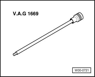
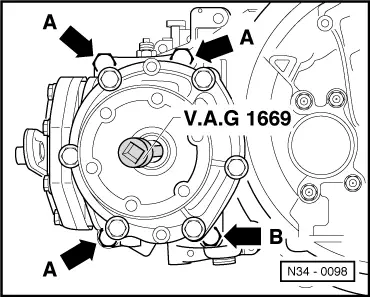
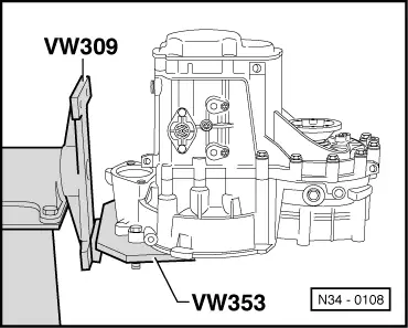
| Special tools and workshop equipment required |
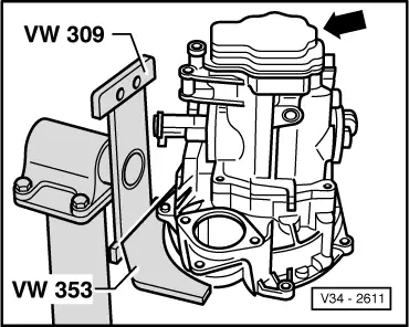
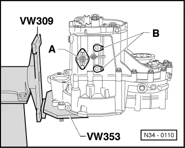
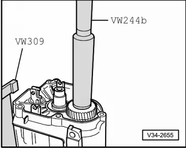
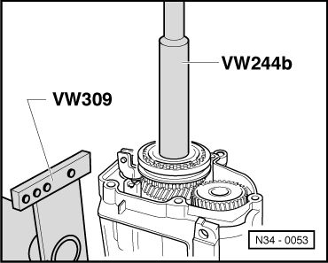
| t | Support plate -VW 309- |
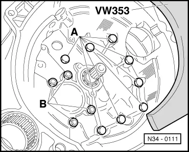
| t | Gearbox support -VW 353- |
| t | Drift -VW 295- |
| t | Drift sleeve -VW 244 B- |
| t | Hot air blower -V.A.G 1416- |
| t | Torque wrench -V.A.G 1331- |
|
|
|
|
|
|
 Note
Note
|
|
|
|
|
|
Note
|
|
|
|
Note
|
|
|
|
|
|
|
|
|
|
|
|
Note
|
|
|
|
|
|
|
|
|
|
Note
|
|
|
|
|
|
Note
|
|
|
|
|
|
|
|
|
|
|
|
|
|
|
|
|
|
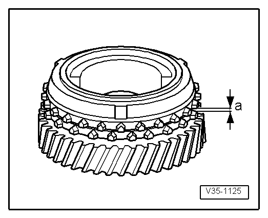
| Gap -a- | Installation (new) dimension | Wear limit |
| 5th gear | 1,1 ... 1.7 mm | 0.5 mm |
|
|
|
|
|
Note
|
|
|
|
|
|
|
|
|
|
|
|
|
|