volkswagen Workshop Repair Guides

Volkswagen Workshop Service and Repair Manuals

Repairing selector mechanism > < Removing and installing Haldex coupling pump V181
Electrical check of Haldex coupling
   
Electrical check of Haldex coupling
Special tools and workshop equipment required
t  Hand multimeter -V.A.G 1526 A-
t  Vehicle diagnosis, testing and information system -VAS 5051-
t  Diagnostic cable -VAS 5051/1- or -VAS 5051/3-
t  Auxiliary measuring set -V.A.G 1594 A-

Additional required information
t  “Current Flow Diagrams, Electrical Fault-Finding and Fitting Locations” folder
Test steps only apply for:
t  Cars (up to 05.99) not capable of diagnosis → Anchor.
Test preconditions
t  Function of Haldex coupling OK; checking → Chapter.
t  Oil level of Haldex coupling OK; checking → Chapter.
t  All fuses according to current flow diagram OK (remove fuses from holder to check them).
t  Voltage supply OK (at least 10.0 V)
t  Brake light OK
t  Correct engine control unit and ABS control unit installed (check coding and control unit identification numbers).
Overview of test steps
   
Component to be tested 
Voltage supply to four-wheel drive control unit -J492-
–  Perform test step 1
Function of brake light switch -F-
–  Perform test step 2
Function of handbrake warning switch -F9-
–  Perform test step 3
Inspection of data bus cables
–  Perform test step 4
Function of Haldex coupling pump -V181- and
function of oil pressure control motor -V184-.
–  Perform test step 5

Performing electrical test.
–  Switch off ignition for all test steps.
–  Raise vehicle.
   
–  Separate connector on rear final drive.
  Note
t  Use hand multimeter -V.A.G 1526 A- and auxiliary cables from -V.A.G 1594 A- for testing.
t  The correct measuring range must be selected each time before auxiliary cables are connected. Otherwise electronic components can be destroyed!
  N01-0320
Contact assignment of connector
1 - Supply voltage (terminal X)
2 - Earth (terminal 31)
3 - Positive connection, terminal 54 (brake light, brake light switch)
4 - Handbrake warning switch -F9-
5 - K-wire for diagnosis
6 - Vacant
7 - Data bus connection to engine control unit and ABS control unit (CAN low).
8 - Data bus connection to engine control unit and ABS control unit (CAN high).
Test step 1
Check of voltage supply from four-wheel drive control unit -J492-.
–  Switch to 20 V measuring range.
–  Switch on ignition.
  N01-0321
–  Measure between contact 1 and contact 2 (earth) on detached connector.
Specification: battery voltage
If specification is not obtained, repair wiring referring to current flow diagram. → "Current Flow Diagrams, Electrical Fault-Finding and Fitting Locations"
–  Switch off ignition.
Test step 2
Check of brake light switch -F- function.
–  Switch to 20 V measuring range.
–  Switch on ignition.
  N01-0321
–  Measure between contact 3 and contact 2 (earth) on detached connector.
Specification: less than 0.5 V
–  Operate brake pedal.
Specification: battery voltage
If specifications are not obtained, repair wiring referring to current flow diagram. → "Current Flow Diagrams, Electrical Fault-Finding and Fitting Locations"
If specifications are still not obtained, renew brake light switch -F- → Brake systems; Rep. Gr.46.
Test step 3
Check of function of handbrake warning switch -F9-.
–  Switch to 20 V measuring range.
–  Switch on ignition.
  N01-0321
–  Measure between contact 4 and contact 2 (earth) on detached connector.
Specification: greater than 6 V
–  Apply handbrake.
Specification: less than 0.5 V
If specifications are not obtained, check wiring to dash panel insert (T32a/13) for open circuit or short circuit to positive. → "Current Flow Diagrams, Electrical Fault-Finding and Fitting Locations"
If specifications are not obtained, check wiring from contact -T32/1- (dash panel insert) via fuse no. 11 (5 A) to terminal 15.
If no fault can be found, renew handbrake warning switch -F9- → Brake systems; Rep. Gr.46.
Test step 4
Check of function of data bus wiring.
–  Switch to 2 k Ω measuring range.
  N01-0321
–  Measure between contact 7 and contact 8 (earth) on detached connector.
Specifications: 50 … 70 70 Ω
If specification is not obtained
–  Check data bus wiring according to current flow diagram for open circuit or short circuit or improper routing. To do this, pull off multi-pin connector for all control units connected to the data bus.
–  Switch to 20 MΩ measuring range.
–  Perform the following resistance checks on disconnected connector of control unit -J492-:
  N01-0321
Between contactsSpecification
7 + 8∞ Ω
7 + 1∞ Ω
8 + 1∞ Ω
7 + 2∞ Ω
8 + 2∞ Ω

–  Also check data bus wires for open circuit. Wire resistance: maximum 1.5 Ω
If specifications are not obtained
–  Repair wiring according to current flow diagram. → "Current Flow Diagrams, Electrical Fault-Finding and Fitting Locations"
If specifications are obtained
–  Reconnect multi-pin connector of all control units, read fault memories of all control units connected to data bus and rectify faults, if any.
Test step 5
Check of function of Haldex coupling pump -V181- and function of oil pressure control motor -V184-.
   
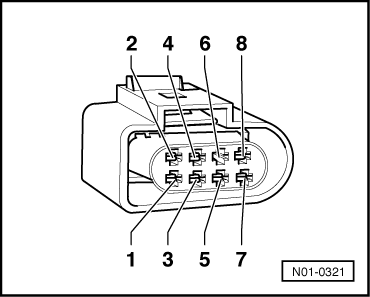
–  Join connector for four-wheel drive control unit -J492-.
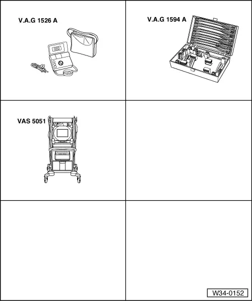
–  Connect vehicle diagnosis, testing and information system -VAS 5051- → Chapter.
–  Apply handbrake.
–  Start vehicle.
–  Operate clutch pedal and engage 1st gear.
–  Drive off slowly, whereby it must be observed that rear wheels attempt to drive against handbrake.
  Note
Release clutch slowly or engine will stall.
If it is not observed that rear wheels attempt to drive against handbrake
t  Check 2-pin connector on Haldex coupling pump -V181- and check wiring according to current flow diagram. → "Current Flow Diagrams, Electrical Fault-Finding and Fitting Locations"
t  
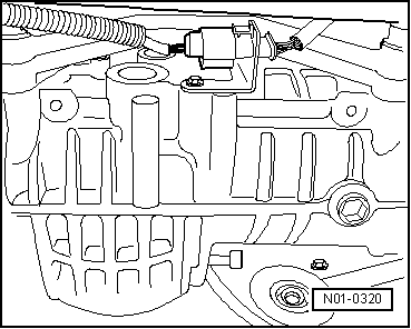
If no fault could be found, then oil pressure control motor -V184- is defective.
  Note
The oil pressure control motor -V184- is integrated in the four-wheel drive control unit.
If it is observed that rear wheels attempt to drive against handbrake
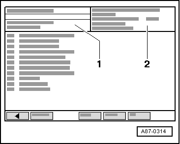
–  Operate clutch pedal and select vehicle system “03 - Brake electronics” on -VAS 5051-.
  N01-0320
–  The control unit identification is displayed in field -2- of the vehicle diagnosis, testing and information system.
–  After the control unit has reported, drive off again in 1st gear with handbrake applied.
Only the front wheels should turn.
If it is still observed that the rear wheels attempt to drive against the handbrake, then the four-wheel drive control unit is defective.
–  Renew four-wheel drive control unit -J492- → Chapter.
  A87-0314

Repairing selector mechanism > < Removing and installing Haldex coupling pump V181