volkswagen Workshop Repair Guides

Volkswagen Workshop Service and Repair Manuals

Adjusting gear selector mechanism from 05.99 > < Assembly overview - removing and installing selector cables
5-speed manual gearbox 02J
Servicing gear selector mechanism from 05.99
Removing and installing selector mechanism
 
N34-0860

Removing

Selector mechanism up to 12.00

  • ‒ → Lever gate selector cable -A- and gear selector cable -B- off gearbox using an open jaw spanner.

1 = 13 mm open jaw spanner, commercially available

Selector mechanism from 01.01

 
N34-1469
  • ‒ → Remove securing clip -3- for gear selector cable from gear selector lever -1-.
  • ‒ Remove securing clip -4- for gate selector cable from relay lever -2-.
  • ‒ Lever gate selector cable and gear selector cable off pin (arrows).

Continued for all selector mechanism

 
V34-2671
  • ‒ → Remove cable support bracket from gearbox (arrows), if necessary unclip hose at cable support bracket first.
 
A34-0026
  • ‒ → Carefully lever the cover off the centre console (arrows).
  • ‒ Pull cover to rear off the centre console.
 
A34-0028
  • ‒ → Destroy clip (arrow) and pull gear stick knob off with cover.
  • ‒ Remove rubber cover, if fitted.
 
N34-1085
  • ‒ → Now remove the gear stick housing front securing nuts (arrows).
 
A34-0025
  • ‒ → Separate front exhaust pipe -A-.

=> Repair group 26; Removing and installing parts of the exhaust system.

  • ‒ Remove cross support -B- below exhaust system.
  • ‒ Loosen heat shield -C- in forward area.
  • ‒ Remove heat shield -D-.
  • ‒ Unbolt selector housing from body.
  • ‒ Swing gear stick housing down and remove with selector cables.
 
N34-1027

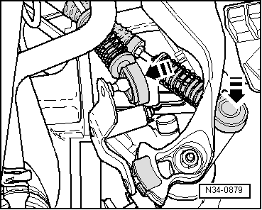
Installing

Installation is carried out in the reverse sequence, when doing this note the following:

Selector mechanism up to 12.00

If you want to reuse cables, you must replace cable locking mechanisms.

  • ‒ → Coat a small amount of grease part No. G 000 450 02 in ball recess of cable locking mechanism -A- and -B-.

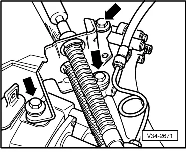
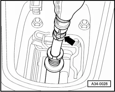
Note:

The seals -arrows- outside the recess must be grease free.

 
N34-0879
  • ‒ → Press gear selector cable onto gearbox selector lever and gate selector cable onto relay lever (arrows).

Selector mechanism from 01.01

 
N34-1468

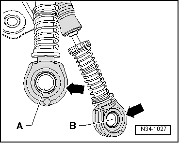
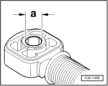
The cable locks have holes for securing them on the gear selector lever or the relay lever.

The holes in the cable locks have various diameters.

→ Allocation

Cable lock for:

Dimension "a"

Gear selector cable to gear change lever

10 mm

Gate selector cable to relay lever

8 mm

The cable locks no longer need to be renewed following dismantling.

 
N34-1469
  • ‒ → Coat a small amount of grease part No. G 000 450 02 on the pins -arrows- of the gear change lever -1- and the relay lever -2-.
  • ‒ Always renew securing clips -3- and -4- after dismantling.
  • ‒ Secure gear selector cable with securing clip -3- and gate selector cable with securing clip -4-.

Continued for all selector mechanisms

  • ‒ Align gear stick housing parallel to body.
  • ● Distance to body must be same on both sides.
  • ‒ Reconnect exhaust system.

=> Repair group 26; Removing and installing parts of the exhaust system.

Cross member to body

=> Repair group 26; Removing and installing parts of the exhaust system.

Adjusting selector mechanism .

Tightening torques

Gear stick housing to body => page 34-38 , item 26

Selector cable support bracket to gearbox => page 34-41 , item 9

Adjusting gear selector mechanism from 05.99 > < Assembly overview - removing and installing selector cables