volkswagen Workshop Repair Guides

Volkswagen Workshop Service and Repair Manuals

Final drive, differential, differential lock > < Dismantling and assembling input shaft
5-speed manual gearbox 02T
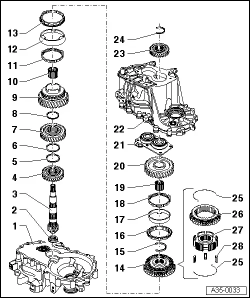
Dismantling and assembling output shaft
 
G35-0004

Special tools, workshop equipment, test and measuring appliances and auxiliary items required

  • ◆ VW 402 Thrust plate
  • ◆ VW 407 Press tool
  • ◆ VW 412 Press tool
  • ◆ VW 415 A Tube
  • ◆ VW 432 Press piece
  • ◆ 40-21 Press tool
 
W00-0633

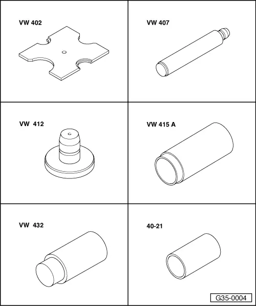
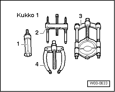
Special tools, workshop equipment, testers, measuring instruments and auxiliary items required

  • ◆ 1 - Kukko 21/5 internal puller
  • ◆ 4 - Kukko 22/1 counter-support
 
A35-0033

Notes:

  • ◆ When installing new gears or a new output shaft consult technical data
    .
  • ◆ Fit all bearings, selector gears and synchro-rings to output shaft with gearbox oil.
  • ◆ Do not interchange synchro-rings. If rings do not need renewing, fit to original selector gear.
  • Clutch housing
  • Roller bearing
    • ◆ With circlip
    • ◆ Pulling out => Fig.1
    • ◆ Pressing in => Fig.2
    • ◆ Fitting location: The circlip in the bearing faces the output shaft
 
A35-0033
  • Output shaft
    • ◆ When an inner race, which is used as a bearing seat for the cylinder roller bearing (item 2 ), then it cannot be removed from output shaft
    • ◆ Check bearing seat or inner race as applicable for scoring and damage
    • ◆ If bearing seat/inner race scored or damaged replace output shaft and cylinder roller bearing together
  • 4th gear
    • ◆ Fitting location: Collar faces 3rd gear => Fig.5
  • Circlip
  • Circlip
 
A35-0033
  • 3rd gear
    • ◆ Fitting location: Collar faces 4th gear => Fig.5
  • Circlip
  • Selector gear for 2nd gear
  • Needle roller bearing
    • ◆ For 2nd gear
  • 2nd gear inner ring
    • ◆ Checking for wear
      => Fig.6
    • ◆ Installation position => Fig.8
  • 2nd gear outer ring
    • ◆ Place on inner ring -item 11 -
    • ◆ Renew if scored
    • ◆ Installation position => Fig.8
  • 2nd gear synchro-ring
    • ◆ Checking for wear
      => Fig.7
    • ◆ Installation position => Fig.8
 
A35-0033
  • 1st and 2nd gear locking collar with synchro-hub
    • ◆ Press off together with selector gear for 2nd gear after removing the circlip (item15 )
      => Fig.4
    • ◆ Dismantling => Fig.9
    • ◆ Assembling locking collar/synchro hub => Fig.9 and Fig.10
    • ◆ Installation position => Fig.9
    • ◆ Pressing on => Fig.11
  • Securing clip
    • ◆ Removing => Fig.3
    • ◆ Inserting => Fig.12
  • 1st gear synchro-ring
    • ◆ Checking for wear
      => Fig.7
    • ◆ Insert so that the locking pieces of the locking collar locate in the inserts -item 14 -
 
A35-0033
  • 1st gear outer ring
    • ◆ Insert in synchro-ring (item 16 ). Installation position => Fig.13
    • ◆ Renew if scored
  • 1st gear inner ring
    • ◆ Checking for wear
      => Fig.6
    • ◆ Check lugs for scoring
    • ◆ Installation position => Fig.14
  • Needle roller bearing
    • ◆ For 1st gear
  • 1st selector gear
    • ◆ Installation position => Fig.15
 
A35-0033
  • Bearing mounting with grooved ball bearings
    • ◆ Only renew grooved ball bearings together with bearing mounting
    • ◆ If bearing mounting is separated from gearbox housing, it must always be renewed
    • ◆ Pressing off , Fig.3
    • ◆ Pressing on => Page 35-16 , Fig.13
  • Gearbox housing
  • 5th gear wheel
    • ◆ Installation position: Collar faces gearbox casing cover => Page 34-71
  • Circlip
    • ◆ Always renew
    • ◆ Determining thickness => Page 34-71
 
A35-0033
  • Spring
    • ◆ Installation position => Fig.10
  • Locking collar
  • Synchro-hub
  • Locking pieces (Qty. 3)
 
A35-0034

→ Fig.1     Pulling roller bearing out of clutch housing

  • ‒ When pulling out, press roller bearing circlip -arrow- together using pliers -C-.

A - Counter support, e.g. Kukko 22/1

B - Internal puller 30...37 mm, e.g. Kukko 21/5

 
A35-0035

→ Fig.2     Pressing roller bearing in clutch housing

  • ‒ Support clutch housing using tube VW 415 A (not visible in diagram) directly under bearing mounting.
  • ‒ When pressing in, press roller bearing circlip -arrow- together using pliers -A-.
  • ‒ Remove pliers just before the roller bearing is in position. The circlip must locate in the groove of the clutch housing.
 
A35-0036

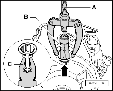
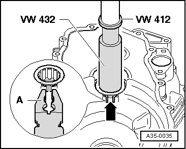
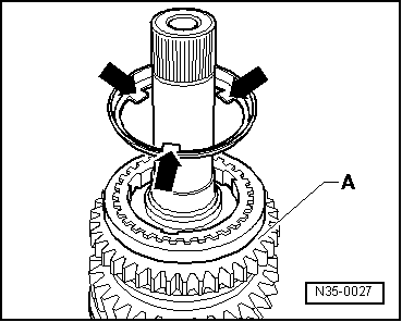
→ Fig.3     Removing circlip -1- from groove

  •      A -     Protective glove
Warning!
Prevent circlip from springing off uncontrolled.
 
A35-0037

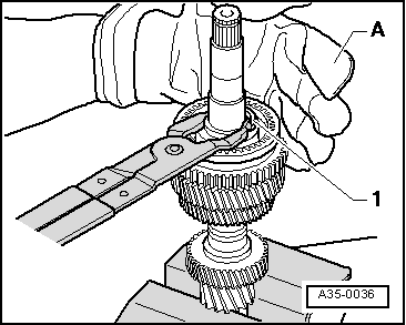
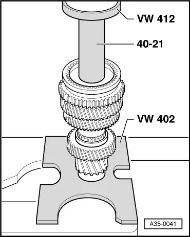
→ Fig.4     Pressing off 1st and 2nd gear locking collar/synchro-hub

  • ‒ When circlip has been removed, press off selector gear for 2nd gear together with locking collar/synchro-hub.
 
A35-0038

→ Fig.5     Installation position of 3rd and 4th gear wheel

  • ‒ Fit 4th gear wheel -A- onto output shaft.

Installation position:

Collar -arrow 1- faces 3rd gear wheel -B-.

  • ‒ Fit circlips -2- and -3-.
  • ‒ Fit 3rd gear wheel -B- onto output shaft.

Installation position:

Collar -arrow 2- faces 4th gear wheel -A-.

  • ‒ Fit circlip -1-.
 
V35-1138

→ Fig.6     Checking 1st and 2nd gear inner ring for wear

  • ‒ Press inner ring onto cone of selector gear and measure gap "a" using a feeler gauge.

Gap "a"

New dimension

Wear limit

1st and 2nd gear

0.75 ... 1.25 mm

0.3 mm

 
V35-1137

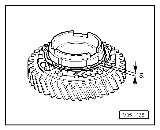
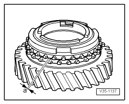
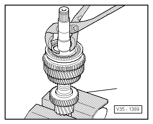
→ Fig.7     Checking 1st and 2nd gear synchro-ring for wear

  • ‒ Press synchro-ring, inner ring and outer ring onto cone of selector gear and measure gap "a" using feeler gauge.

Gap "a"

New dimension

Wear limit

1st and 2nd gear

1.2 ... 1.8 mm

0.5 mm

 
N35-0029

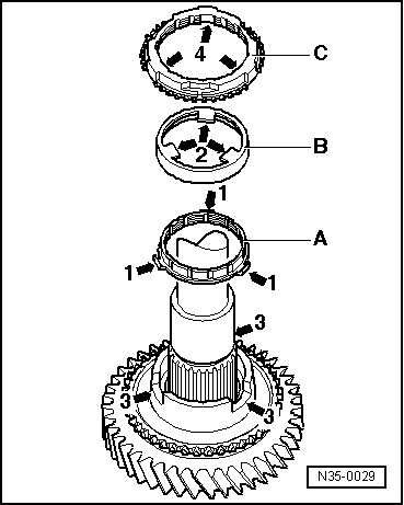
→ Fig.8     Installation position of outer ring, inner ring and synchro-ring of 2nd gear

  • ‒ Place inner ring -A- on selector gear of 2nd gear.
  • The angled tabs -arrow 1- point towards the outer ring -B-.
  • ‒ Fit outer ring -B-.
  • The tabs -arrow 2- lock in the recesses -arrow 3- of the selector gear.
  • ‒ Fit synchro-ring -C-.
  • The recesses -arrow 4- locate on the tabs -1- of the inner ring -A-.
 
A35-0039

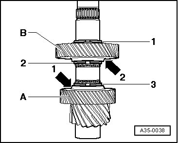
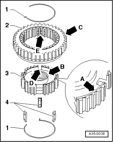
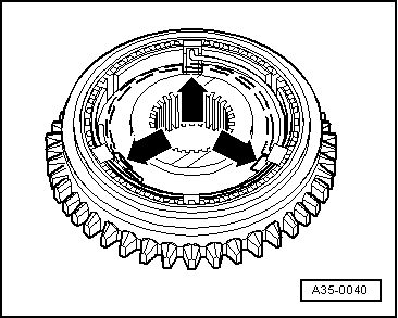
→ Fig.9     Dismantling and assembling 1st and 2nd gear locking collar and synchro-hub

  •      1 -     Circlip
  •      2 -     Locking collar
  •      3 -     Synchro-hub
  •      4 -     Locking piece
  • ‒ Slide locking collar over synchro-hub.

Installation position:

The groove on the top -arrow A- and the higher collar -arrow B- of the synchro-hub face the gear teeth of the locking collar when fitted together -arrow C-.

The deeper recesses -arrow D- for the locking pieces in the synchro-hub must align with the recesses -arrow E- in the locking collar.

 
A35-0040

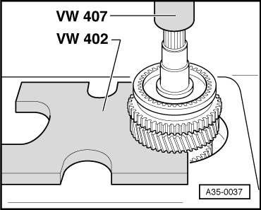
→ Fig.10     Assembling 1st and 2nd gear locking collar/synchro-hub

  • ● Locking collar is pushed over synchro-hub.
  • ‒ Insert locking pieces in deeper recesses -arrows- and install springs 120° off-set. The angled end of the spring must locate in the hollow locking piece.
 
A35-0041

→ Fig.11     Pressing on 1st and 2nd gear locking collar/synchro-hub

Installation position:

The groove in the locking collar for the selector fork faces the 1st gear and the reverse gear teeth face the 2nd gear.

  • ‒ Turn synchro-ring so that the grooves are flush with the locking pieces.
 
V35-1389

→ Fig.12     Inserting circlip

  • ‒ Fit 1st gear synchro-ring in locking collar/synchro-hub.
 
N35-0027

→ Fig.13     Installation position for 1st gear outer ring

The lugs (arrows) face the gear teeth of the reverse gear

 
N35-0028

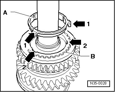
→ Fig.14     Installation position of 1st gear inner ring -A-

The lugs (arrow 1) locate in the recesses (arrow 2) in the synchro-ring -B-.

 
A35-0042

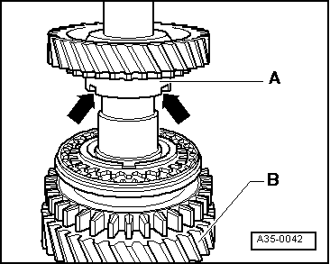
→ Fig.15     Installation position of selector gear for 1st gear

The higher collar -A- faces the 2nd gear -B-. The recesses in the collar (arrows) locate with the tabs of the outer ring (arrow => Fig.13 )

Final drive, differential, differential lock > < Dismantling and assembling input shaft