
Golf Mk4
|
Dismantling and assembling input shaft
Dismantling and assembling input shaft
|
 |
|
|
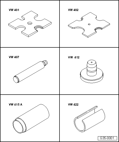
Special tools, workshop equipment, test and measuring appliances and auxiliary items required
|
 |
|
|
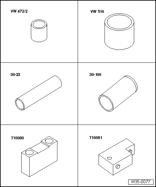
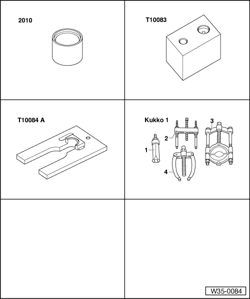
Special tools, workshop equipment, test and measuring appliances and auxiliary items required
|
 |
|
|
Notes:
|
|
|
|
|
|
|
|
|
|
|
|
|
|
 |
|
|
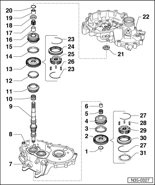
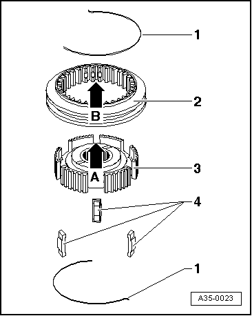
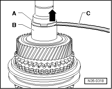
→ Fig.7 Installation position 3rd and 4th gear locking collar/synchro-hub The groove on the top (arrow B) points towards 4th gear. |
 |
|||||||
|
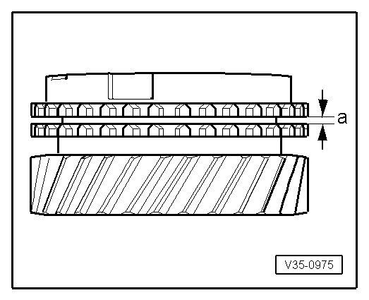
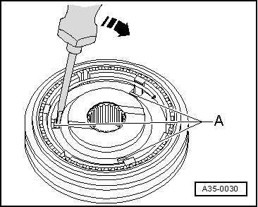
→ Fig.8 Checking synchro-ring for wear
|
 |
|
|
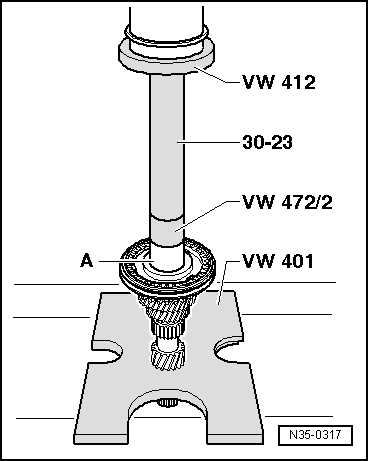
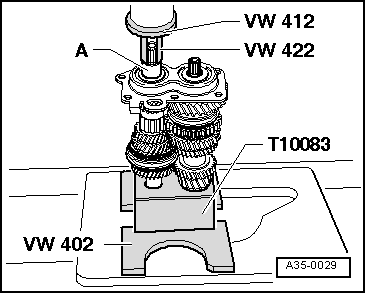
→ Fig.9 Pressing on 3rd and 4th gear synchro-hub and locking collar |
 |
|
|
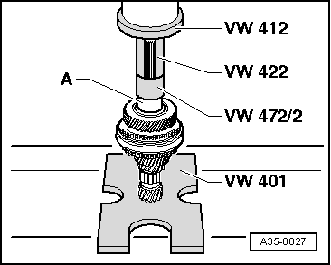
→ Fig.10 Pressing on sleeve -A- for 4th gear needle roller bearing
|
 |
|
|
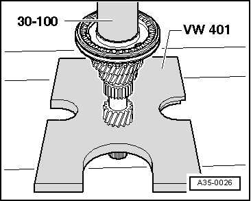
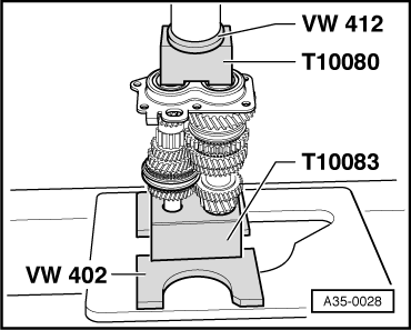
→ Fig.11 Pressing on roller bearing inner race -A- |
 |
|
|
→ Fig.13 Pressing on bearing mounting with grooved ball bearings
Warning!
Wear protective gloves! |
 |
|
|
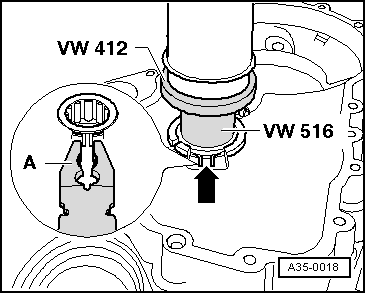
→ Fig.14 Pressing on sleeve -A- for 5th gear needle roller bearing |
 |
|
|
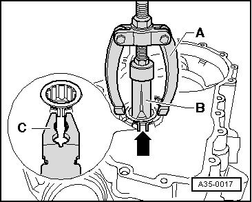
→ Fig.15 Removing thrust ring
|
 |
|
|
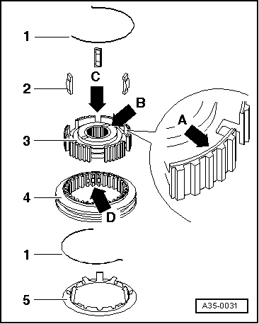
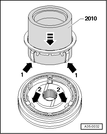
→ Fig.16 Dismantling and assembling 5th gear locking collar and synchro-hub
The deeper recesses -arrow C- for the locking pieces in the synchro-hub must align with the recesses -arrow D- in the locking collar. |
 |
|
|
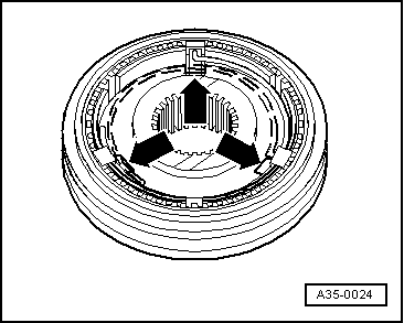
→ Fig.17 Assembling 5th gear locking collar/synchro-hub
|
 |
|
|
→ Fig.18 Installing check ring
|