volkswagen Workshop Repair Guides

Volkswagen Workshop Service and Repair Manuals

Removing and installing cylinder head > < Removing
Installing
Installing
–  Check whether TDC mark on flywheel and reference mark are aligned.
–  Loosen securing bolt of camshaft pulley one turn. To loosen securing bolt of camshaft pulley, secure with counterhold 3036.
  Note
Never use camshaft bar -T10098 A- as a counterhold to loosen and tighten camshaft pulley! Use counterhold -3036-.
   
–  Position two arm puller -T40001- with single arm hook -T40001/2--A- and two arm hook -T40001/3--B- centrally on camshaft pulley and pull pulley off. When doing this, use an open-end spanner as a counterhold -C-.
–  Fit toothed belt on crankshaft belt pulley, idler roller, injection pump pulley, coolant pump pulley and tensioning roller (note direction of rotation).
–  Align injection pump pulley centrally in elongated holes.
  N15-10157
–  Fit camshaft pulley together with toothed belt and fix with securing bolt (camshaft pulley can still be turned).
–  Tension toothed belt. To do this, turn Matra pin wrench -V159-) clockwise on eccentric until notch and protrusion -arrows- are aligned.
  Note
If eccentric has been turned too far, tensioning roller must be completely relieved of tension and retensioned. The eccentric must not simply be turned back by the amount it has been turned too far.
–  Tighten clamping nut on tensioning roller. Specified torque: 20 Nm.
  Note
  A13-0050
Ensure that tensioning roller seats correctly in rear toothed belt guard -arrow-.
–  Check TDC mark on flywheel again.
–  Tighten camshaft pulley securing bolt to 45 Nm.
  A13-0053
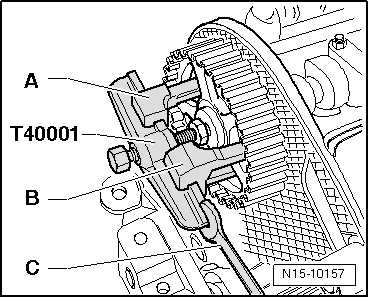
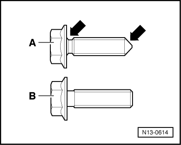
Type -A-: securing bolts with milled neck and tapered end -arrow-
–  Tighten new securing bolts of injection pump belt pulley. Specified torque: 20 Nm.
  Note
t  Following dynamic check of commencement of injection, securing bolts should be tightened further by 90° (1/4 turn).
t  The securing bolts should only be used once as these are stretch bolts.
Type -B-: securing bolts without milled neck and with flat end
–  Tighten old securing bolts of injection pump belt pulley. Torque setting: 25 Nm.
  Note
Do not renew securing bolts.
Continuation for all versions
–  Remove camshaft bar -T10098 A- from camshaft.
–  Remove locking pin.
–  Turn crankshaft two rotations in engine DOR and set again to TDC no. 1 cylinder.
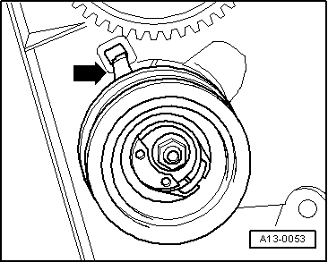
–  Check TDC marking on flywheel, whether camshaft bar fits in camshaft, whether locking pin fits in injection pump belt pulley, adjustment of tensioning roller (notch/protrusion or notch/arrow).
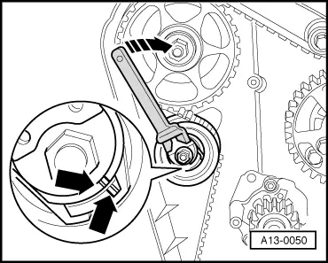
–  If notch and protrusion or notch and arrow are not aligned, adjust tension of tensioning roller and tighten securing nut to 20 Nm.
–  Turn crankshaft two rotations in engine D.O.R. until crankshaft is set to TDC No. 1 cylinder again.
–  Repeat check.
  N13-0614
–  Fit engine bracket to cylinder block and tighten -arrows-. Torque setting: 45 Nm.
  Note
Before installing assembly mounting, tighten all engine bracket bolts to specified torque.
–  Install engine to body assembly mounting(renew securing bolts). Torque setting: 40 Nm + 90° (1/4 turn)
–  Align assembly mounting on engine side → Chapter.
–  Fit engine assembly mounting to engine bracket by bringing contact surfaces together using support bracket 10-222 A. Torque setting: 100 Nm.
–  Align assembly mounting on engine side → Chapter.
–  Install assembly mounting bracket on body. Torque setting: 25 Nm.
–  Install coolant expansion tank.
–  Install power steering reservoir.
–  Install vacuum pump. Torque setting: 20 Nm.
–  Install toothed belt guard and vibration damper/belt pulley.
–  Install poly V-belt → Chapter.
–  Install noise insulation.
Engine codes AGR, AHF, ALH, ASV
–  Install connecting pipe between charge air cooler and intake manifold → Chapter.
–  Install right headlight: → Rep. Gr.94
–  Check headlight adjustment and correct if necessary .
Continuation for all engine codes
–  Check commencement of injection of injection pump: → Rep. Gr.23
  N13-0699

Removing and installing cylinder head > < Removing