
Golf Mk4
| Parts of cooling system - body side |
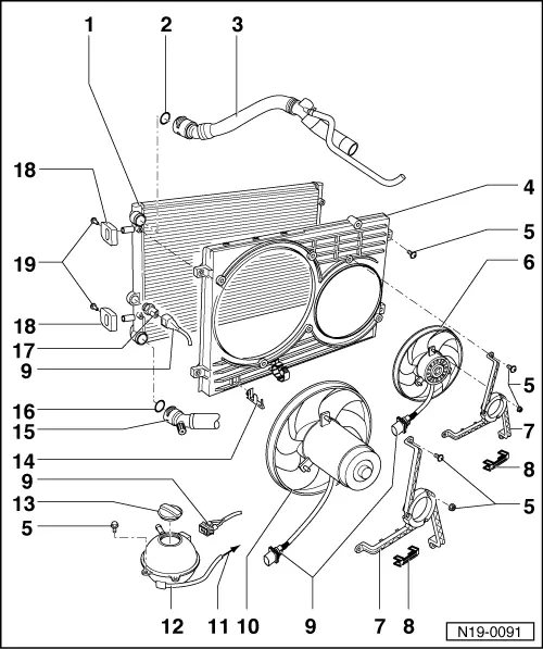
| 1 - | Radiator |
| q | Removing and installing → Chapter |
| q | After renewing, renew entire coolant. |
| 2 - | O-ring |
| q | Renew |
| 3 - | Upper coolant hose |
| q | Secured to radiator with retaining clip. |
| q | Coolant hose schematic diagram → Chapter. |
| 4 - | Cowling |
| 5 - | 5 Nm |
| 6 - | Additional fan |
| q | Only vehicles with optional equipment. |
| 7 - | Fan ring |
| 8 - | Securing clip |
| q | Check for secure seating. |
| 9 - | Connector |
| 10 - | Radiator fan |
| 11 - | To coolant pipe |
| q | Coolant hose schematic diagram → Chapter. |
| 12 - | Expansion tank |
| q | Test cooling system for leaks using cooling system tester -V.A.G 1274- and adapter for cooling system tester -V.A.G 1274/8-. |
| q | Test pressure 1.4…1.6 bar |
| q | Observe markings → Chapter Draining and filling coolant |
| 13 - | Cap |
| q | Check using cooling system tester -V.A.G 1274- and adapter for cooling system tester -V.A.G 1274/9-. |
| q | Pressure relief valve must open at between 1.4 and 1.6 bar. |
| 14 - | Bracket |
| q | For fan connector. |
| 15 - | Lower coolant hose |
| q | Secured to radiator with retaining clip. |
| q | Coolant hose schematic diagram → Chapter. |
| 16 - | O-ring |
| q | Renew |
| 17 - | Radiator fan thermal switch -F18-, 35 Nm |
| q | For radiator fan. |
| q | Switching temperatures: stage 1 on: 92…97 °C off: 84…91 °C; stage 2 on: 99…105 °C off: 91…98 °C |
| 18 - | Bracket |
| q | For radiator. |
| q | Note installation position. |
| q | Note various versions. |
| 19 - | 5 Nm |