| –
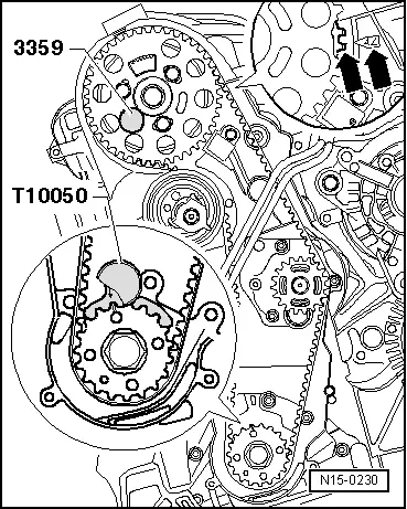
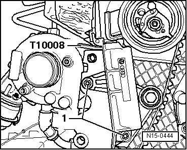
| Tighten bolts -1- of camshaft toothed belt pulley to 25 Nm. |
| –
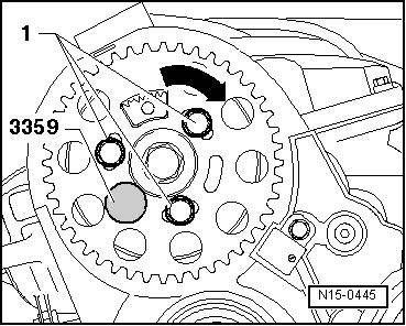
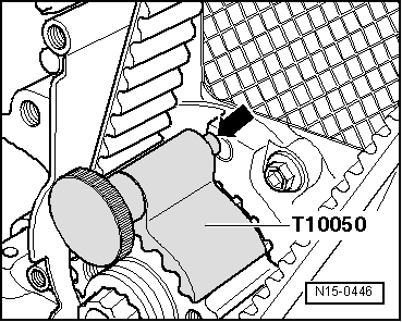
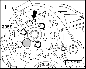
| Remove locking pin for diesel injection pump -3359- and crankshaft stop -T10050-. |
| –
| Turn crankshaft two rotations in engine direction of rotation and set again to TDC no. 1 cylinder. |

Note | t
| When doing this, the crankshaft stop pin must engage in the sealing flange whilst turning. |
| t
| If the crankshaft is turned past TDC no. 1 cylinder and the crankshaft stop could not engage in the sealing flange, turn the crankshaft back 1/4 turn so that the crankshaft can again be turned in engine direction of rotation to allow it to be set to TDC no. 1 cylinder. Making corrections against engine direction of rotation in order to insert the crankshaft stop is not permissible. |
| –
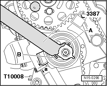
| Once crankshaft stop -T10050- has been inserted, check whether: |
| 1.) Dimension -a- can be reached. |
| 2.) The hub can be locked using locking pin for diesel injection pump -3359-. |
| If dimension -a- is not achieved: |
| –
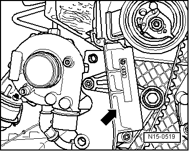
| Tension the tensioning roller again. To do this, counterhold tensioning roller using pin wrench -3387-, loosen securing nut and adjust counterforce of tensioning device until measurement -a- is achieved. Specification -a-: 4 ± 1 mm. |
| –
| Tighten securing nut to 20 Nm and 45° (1/8 turn) further. |
| If the hub cannot be locked: |
| –
| Pull crankshaft stop pin out of drilling in sealing flange and turn crankshaft until hub can be locked with locking pin. |
|
|
|

 WARNING