volkswagen Workshop Repair Guides

Volkswagen Workshop Service and Repair Manuals

Checking function of thermostat > < Dismantling and assembling coolant distribution housing
Checking map-controlled engine cooling thermostat F265
Checking map-controlled engine cooling thermostat -F265-
Special tools and workshop equipment required
t  Fault reader -V.A.G 1551- or vehicle system tester -V.A.G 1552-
t  Diagnostic cable -V.A.G 1551/3C-
t  121-pin adapter cable -V.A.G 1598/31-
t  Hand multimeter -V.A.G 1526C- or multimeter -V.A.G 1715-
t  Auxiliary measuring set -V.A.G 1594A- or auxiliary measuring set -V.A.G 1594C-
Test prerequisites
l  Engine must be cold.
Test procedure
–  Pull 2-pin connector off map-controlled engine cooling system thermostat -F265-.
–  Measure resistance of heater element on map-controlled engine cooling system thermostat -F265- using cables from auxiliary test set -V.A.G 1594A- or auxiliary test set -V.A.G 1594C-. Specification st 25 °C: 14…16 Ω.
If the specification is not obtained:
–  Renew map-controlled engine cooling thermostat -F265-.
If the specification is obtained:
–  Connect fault reader -V.A.G 1551- or vehicle system tester -V.A.G 1552-. Start engine and select engine control unit with “address word” 01. Connect fault reader and select engine control unit → Rep. Gr.01.
   
Indicated on display:
–  Press buttons 0 and 8 for function “Read measured value block” and confirm entry with Q button.
 
Rapid data transfer                 HELP
Select function XX                    
Indicated on display:
–  Press buttons 1, 3 and 2 for “Display group number 132” and confirm entry with Q button.
 
Read measured value block          HELP
Input display group number  XX        
Indicated on display: (1...4 = display zones)
–  Connect multimeter to contacts 1 and 2 of 2-pin connector for thermostat (wiring harness) to measure voltage.
 
Read measured value block 132          -
         1         2         3         4
–  Pull 4-pin connector -1- off coolant temperature sender -G62--2-.
–  Allow engine to continue to run at idling speed and observe right bit in display zone 4, when a “1” is displayed after a few seconds a fault is detected.
–  Now read voltage on multimeter. Specification: approx. alternator voltage.
If the specification is obtained:
–  Reconnect 4-pin connector for coolant temperature sender -G62-.
–  Checking function of thermostat → Chapter.
If the specification is not attained:
–  Switch off engine.
–  Connect multimeter to 2-pin connector contact 1 and earth to measure voltage.
–  Switch on ignition. Specification: at least. 11.5 V.
If the specification is not attained:
–  Check wiring connections to current supply relay for Simos control unit (in protective housing for relays in engine compartment) → Current flow diagrams, Electrical fault finding and Fitting locations. → Current flow diagrams, Electrical fault finding and Fitting locations
If the specification is obtained:
–  Switch off ignition.
  N24-0985
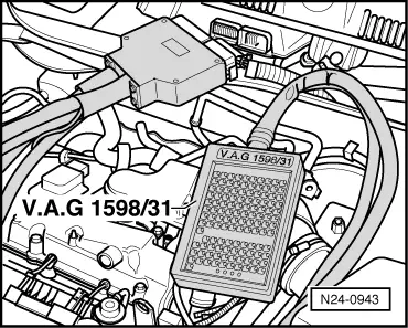
–  Connect 121-pin adapter cable -V.A.G 1598/31- to control unit wiring harness. The engine control unit remains disconnected.
–  Check wiring between 121-pin adapter cable -V.A.G 1598/31- and 2-pin connector for open circuit referring to current flow diagram. Contact 2 and test box socket 116, wire resistance: max. 1.5 Ω.
–  Additionally check wire for short circuit to battery positive and earth. Specification: ∞ Ω.
If no fault is detected in the wiring and the resistance of the heater element is OK., check function of thermostat as follows:
  N24-0943

Checking function of thermostat > < Dismantling and assembling coolant distribution housing