| –
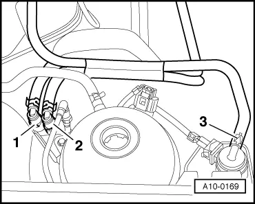
| Pull off supply hose -1- (with white marking) and return hose -2- (with blue marking) and catch fuel that escapes in a cloth. |
| –
| Pull hose off activated charcoal filter system solenoid valve 1 -N80--3-. |

WARNING | Fuel system is under pressure! Before opening the system place a cloth around the connection. Then release pressure by carefully loosening the connection. |
|

Note | Press in securing ring to release fuel lines. |
| –
| Seal lines so that fuel system is not contaminated by dirt. |
| –
| Detach connectors from the following components: |
| t
| Ignition transformer -N152- |
| t
| Injector, cylinder 1 -N30- |
| t
| Injector, cylinder 2 -N31- |
| t
| Injector, cylinder 3 -N32- |
| t
| Injector, cylinder 4 -N33- |
| t
| Coolant temperature sender -G62- |
| t
| Engine speed sender -G28- |
| t
| Exhaust gas recirculation valve -N18- with exhaust gas recirculation potentiometer -G212- |
| t
| Secondary air pump motor -V101- |
| t
| Oil pressure switch -F1- |
| t
| Throttle valve module -J338- |
| t
| If necessary, air conditioning system switch off thermal switch -F163- |
| –
| Remove air filter with intake hose and air mass meter -G70-. |
| –
| Remove upper part of intake manifold. |
Note | Seal intake ports in lower part of intake manifold using a clean cloth. |
| Vehicles with manual gearbox |
Note | Clutch pedal must not be depressed. |
| Vehicles with automatic gearbox |
| Continuation for all vehicles |
| –
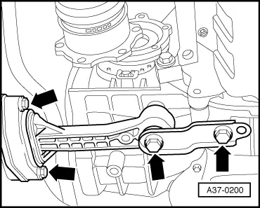
| Remove securing clamps for power-assisted steering pressure line. |
| –
| Unbolt power assisted steering vane pump from bracket and lay to side, hoses remain connected: → Rep. gr.48. |
| Vehicles with air conditioning system: |
| –
| Remove air conditioner compressor: |
| –
| Observe additional information and installation work → Chapter. |
| –
| Remove inter-connecting, coolant, vacuum and intake hoses on engine. |
| –
| Remove secondary air pump and bracket. |
| –
| Disconnect all electrical wiring from gearbox, alternator and starter and lay to side. |
| –
| Pull off or disconnect all other electrical connections as necessary from engine and lay to side. |
|
|
|