volkswagen Workshop Repair Guides

Volkswagen Workshop Service and Repair Manuals

Torque settings > < Securing engine to assembly stand
Notes on installing
Notes on installing
Installation is carried out in the reverse order. When installing, note the following:
  WARNING
When doing any repair work, especially in the engine compartment, pay attention to the following due to the cramped conditions:
t  Route all types of line (e.g. for fuel, hydraulics, active charcoal filter system, coolant, refrigerant, brake fluid and vacuum) and electrical wiring in their original positions.
t  Ensure that there is sufficient clearance to all moving or hot components.
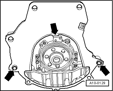
–  Check whether dowel sleeves for centring engine and gearbox are in cylinder block and install if necessary.
   
–  Hook intermediate plate onto sealing flange and slide onto dowel sleeves -arrows-.
Vehicles with manual gearbox
–  Check centring of clutch drive plate, if necessary.
–  Check clutch release bearing for wear and renew if necessary.
–  Lightly lubricate clutch release bearing, release bearing guide sleeve and splines on input shaft with grease -G 000 100-.
Vehicles with 5-speed manual gearbox 02C
–  Install hydraulic clutch slave cylinder: → Rep. Gr.30.
–  Install gear selector mechanism: → Rep. Gr.34.
–  Adjust selector cable, if necessary: → Rep. Gr.34.
Vehicles with 5-speed manual gearbox 02J
–  Install hydraulic clutch slave cylinder: → Rep. Gr.30.
–  Install gear selector mechanism: → Rep. Gr.34.
–  Adjust selector cable, if necessary: → Rep. Gr.34.
Vehicles with 6-speed manual gearbox 02M
–  Install gear selector mechanism: → Rep. Gr.34.
–  Install hydraulic clutch slave cylinder: → Rep. Gr.30.
Vehicles with automatic gearbox
–  Only use nuts approved in parts programme to secure torque converter to drive plate.
–  Install gate lever cable on gearbox, adjust if necessary: → Rep. Gr.37.
Continuation for all vehicles
–  When installing engine and gearbox, ensure that there is sufficient clearance to drive shafts.
–  Align engine and gearbox mountings → Chapter.
–  Install drive shafts: → Rep. Gr.40.
–  Install front exhaust pipe → Chapter.
–  Adjust accelerator cable (vehicles with no EPC) → Chapter.
Vehicles with turbocharger
–  Reconnect intake hose (between charge air cooler and throttle valve control module -J338-) to throttle valve control module -J338- and secure.
Continuation for all vehicles
–  Install power assisted steering vane pump: → Rep. Gr.48.
–  Electrical connections and routing → Rep. Gr.97.
–  Install poly V-belt → Chapter.
–  Install connecting hoses between secondary air pump/combination valve and secondary air pump/air cleaner.
–  Install noise insulation: → Rep. Gr.50.
–  Filling with coolant → Chapter.
–  Adapt engine control unit to throttle valve control module -J338- → Chapter.
–  Vehicles with automatic, the gearbox control unit must also be adapted, → Chapter.
–  Carry out road test and read all fault memories → Chapter
  A10-0129

Torque settings > < Securing engine to assembly stand