
Golf Mk4
| Assembly overview |

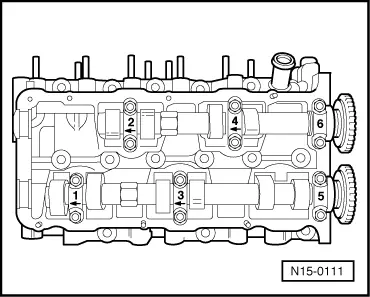
| 1 - | Bearing cap |
| q | Installation position → Fig.. |
| q | Installation sequence → Chapter |
| 2 - | 20 Nm |
| 3 - | Camshafts |
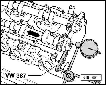
| q | Checking axial clearance → Fig.. |
| q | Removing and installing → Chapter. |
| q | Check radial clearance with Plastigage; wear limit: 0.10 mm |
| q | Runout: max. 0.01 mm. |
| 4 - | Camshaft chain sprocket |
| q | Removing and installing → Chapter. |
| 5 - | Sender wheel |
| q | For Hall sender -G40-. |
| q | When installing contact surface on camshaft chain and sender wheel must be dry |
| q | Removing and installing → Chapter. |
| 6 - | 100 Nm |
| q | To remove and install, counterhold camshaft with AF 24 mm open-jaw spanner → Chapter |
| q | Oil bolt head contact surface when installing |
| 7 - | Cylinder head height |
| q | Minimum height: -a- = 139.5 mm |
| 8 - | Cylinder head |
| q | See note → Chapter. |
| q | Reworking valve seats → Chapter. |
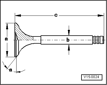
| 9 - | Valves |
| q | Do not rework, only lapping-in is permitted. |
| q | Valve dimensions → Fig. |
| 10 - | Valve guide |
| q | Checking → Chapter. |
| q | Renew → Chapter. |
| q | Service version with collar. |
| 11 - | Valve stem seal |
| q | Renew → Chapter. |
| 12 - | Valve springs |
| q | Removing and installing: |
| q | With cylinder head removed, use valve spring compressor -2037- |
| q | with cylinder head installed → Chapter |
| 13 - | Valve spring plate |
| 14 - | Valve cotters |
| 15 - | Bucket tappet |
| q | Do not interchange. |
| q | With hydraulic valve clearance compensation. |
| q | Checking → Chapter. |
| q | Store with cam contact surface downwards. |
| q | Before installing, check axial clearance of camshafts → Fig. |
| q | Oil contact surface. |
|
|
 Note
Note
|
|
| Dimension | Inlet valve | Exhaust valve | |
| Ø a | mm | 39.0 | 34.20 |
| Ø b | mm | 6.967 | 6.96 |
| c | mm | 105.95 | 106.95 |
| α | ∠° | 45 | 45 |