volkswagen Workshop Repair Guides

Volkswagen Workshop Service and Repair Manuals

Checking data bus > < Checking engine speed sender G28
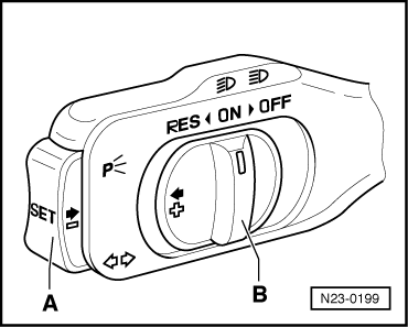
Checking cruise control system (CCS)
The CCS has, apart from the control switches, no components of its own all functions are provided by the diesel direct injection system.
Special tools and workshop equipment required
t  Fault reader -V.A.G 1551- or vehicle system tester -V.A.G 1552- with diagnosis cable -V.A.G 1551/3-
t  
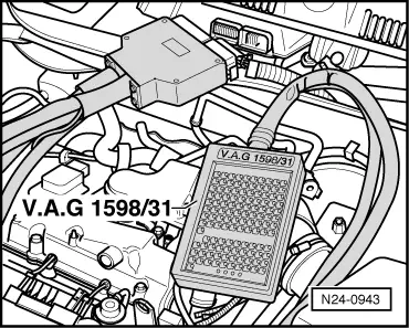
Adapter cable, 121-pin -V.A.G 1598/31-
t  Hand multimeter -V.A.G 1526C- or multimeter -V.A.G 1715-
t  Auxiliary measuring set -V.A.G 1594C-
t  Current flow diagram
Test procedure
–  Connect fault reader -V.A.G 1551- or vehicle system tester -V.A.G 1552- and select engine electronics control unit with “address word 01”. Engine must be idling. (Connecting fault reader and selecting engine electronics control unit → Chapter.)
   
Indicated on display:
–  Press buttonss 0 and 8 for function “Read measured value block” and confirm entry with Q button.
 
Rapid data transfer                 HELP
Select function XX                    
Indicated on display:
–  Press buttons 0, 0 and 6 for “Display group number 6” and confirm entry with Q button.
–  Observe display in display zone 4.
 
Read measured value block           HELP
Input display group number XXX       
Specification: 0 = Cruise control system switched off 1 = Cruise control system switched on
 
Read measured value block 6          ->
    0 km/h     0  0  0     000000     0
If 255 is displayed in display zone 4:
–  Activate cruise control system → Current flow diagrams, Electrical fault finding and Fitting locations
Vehicles with automatic gearbox only:
–  Perform a road test and exceed a speed of 30 km/h (approx. 19 mph) once. Then switch off engine and leave selector lever in position 2, 3 or D.
–  Pull on handbrake.
 
Read measured value block 6           ->
    0 km/h     0  0  0    000000     255
Check display in display zone 3.
 
Read measured value block 6          ->
    0 km/h     0  0  0     000000     0
Test prerequisitesDisplay zone 3
Switch B engaged at “OFF”
000000
Switch B at “OFF”,
before engagement point
000001
Switch B at “ON”000011
Switch B at “RES”001011
Switch A pressed000111
Brake pedal depressed010011
Clutch pedal depressed100011

If the specifications are not achieved:
–  Press button.
–  Press buttons 0 and 6 for function “End output” and confirm entry with Q button.
–  Switch off ignition.
   
–  Connect adapter cable, 121-pin -V.A.G 1598/31- to control unit wiring harness.
  N23-0199
–  Switch on ignition.
  N24-0943
–  Connect multimeter to measure voltage between the following sockets of adapter cable, 121-pin -V.A.G 1598/31- and measure voltage at the specified switch positions.
–  Socket 4/5 + 45 switch B to “ON” = 0 V switch B to “RES” = battery voltage
–  Socket 4/5 + 44 switch A not pressed = 0 V switch A pressed = battery voltage
–  Socket 4/5 + 14 switch B to “OFF” = 0 V switch B to “ON” = battery voltage
–  Socket 4/5 + 46 switch B to “OFF” = 0 V switch B to “ON” = battery voltage
If the specifications are not achieved:
–  Measure voltage on operating switch directly. → Current flow diagrams, Electrical fault finding and Fitting locations
  N23-0199

Checking data bus > < Checking engine speed sender G28