volkswagen Workshop Repair Guides

Volkswagen Workshop Service and Repair Manuals

Check misfiring recognition > < Checking ignition coils with output stage
Motronic injection and ignition system (2.0 ltr. engine)
Servicing ignition system
Checking knock sensor

Notes:

  • ◆ It is extremely important to keep to the tightening torque of 20 Nm to ensure the knock sensors perform perfectly.
  • ◆ Only gold-plated contacts may be used when servicing the knock sensor connector contacts.

Special tools, workshop equipment, testers, measuring instruments and auxiliary items required

  • ◆ Test box V.A.G 1598/22
  • ◆ Hand multimeter V.A.G 1526 or multimeter V.A.G 1715
  • ◆ Adapter set V.A.G 1594
  • ◆ Current flow diagram

Test conditions

  • ● Self-diagnosis must have recognized a fault on one or both knock sensors.

Checking function

  • ‒ Connect fault reader V.A.G 1551 (V.A.G 1552). Start engine and select "Address word" 01 of engine control unit. When doing this the engine must be running at idling speed.
    (Connecting fault reader and selecting engine control unit .)
 
→ Indicated on display:
Rapid data transfer     HELP
Select function XX
  • ‒ Press keys 0 and 8 for the function "Read measured value block" and confirm entry with Q key.
 
→ Indicated on display:
Read measured value block     HELP
Input display group number XXX
  • ‒ Press keys 0, 2 and 2 for the "Display group number 22" and confirm entry with Q key.
 
→ Indicated on display:
(1...4 = Display zones)
Read measured value block 22     ⇒
     1     2     3     4

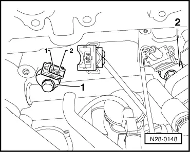
Note:

Checking the knock sensors must be performed during a test drive because the diagnosis of the knock sensors is first activated above an engine speed of 3000 rpm and an engine load greater than 3 ms.

Observe the valid safety precautions when carrying out a test drive => Page 28-5 .

  • ‒ Perform a test drive and check knock control specifications on display (display zones 3 and 4)
  •      Specification (cylinders 1 and 2): 0...15 °CA
  • ‒ Change to display group 23 as follows:
  • ‒ Press key 3 (V.A.G 1551) or key ↑(V.A.G 1552).
 
→ Indicated on display:
(1...4 = Display zones)
Read measured value block 23     ⇒
     1     2     3     4
  • ‒ Check knock control specifications on display (display zones 3 and 4)
  •      Specification (cylinders 3 and 4): 0...15 °CA

If the specifications are obtained:

  • ‒ Press ⇒key.
  • ‒ Press keys 0 and 6 for the "End output" function and confirm input with the Q key.
  • ‒ Switch off ignition.

If the specifications are not attained:

 
N28-0148

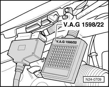
Checking resistances and wiring

  • ‒ → Separate the 2-pin connector to knock sensor 1 (G61) -1- and/or 2-pin connector to knock sensor 2 (G66) -2-.
  • ‒ Measure resistance between the contacts 1+2 at connections to knock sensors.
         Specification ∞ω
 
N24-0709
  • ‒ → Connect test box V.A.G 1598/22 to control unit wiring harness.
  • ‒ Check wiring between test box and 2-pin connector for open circuit according to current flow diagram.
              G61:     G66:
         Contact 1+socket     68     60
         Contact 2+socket     67     67
         Wire resistance: Max. 1.5 ω
  • ‒ Additionally check wires at socket 67 for short to sockets 60 and 68.
         Specification: ∞ω

If no wiring fault is detected:

  • ‒ Loosen knock sensor and tighten again to 20 Nm.
  • ‒ Carry out test drive.
  • During the road test the following operating conditions must be fulfilled:
    • ‒ The coolant temperature must exceed 80 °C .
    • ‒ When the temperature is reached, the operating conditions
           Idling
           Part throttle
           Full throttle
           Overrun
      must be attained several times.
    • ‒ At full throttle the speed must exceed 3500 rpm.
  • ‒ Again interrogate the control unit fault memory.

If the fault is still present:

  • ‒ Replace knock sensor(s)

Check misfiring recognition > < Checking ignition coils with output stage