The wheel bearings must not be loaded while a twelve-point nut or hexagon bolt is loose.
If wheel bearings are loaded with weight of vehicle, bearing will be damaged. This reduces the service life of the wheel bearing.
If a vehicle has to be moved after the drive shaft has been removed, first install an outer joint instead of the drive shaft and tighten to 50 Nm because otherwise the wheel bearing will be damaged.
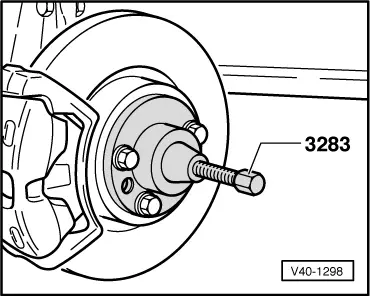
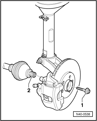
The threaded connection between wheel hub and drive shaft of the “Golf GTI 132 kW” special model and the R32 is made with a hexagon bolt -1- instead of a twelve-point nut. The outer joint splines -2- are slightly shorter than the previous splines and have an internal thread.
Deviating assembly instructions and the modified torque setting can be found in the following procedure.
–
Lift vehicle far enough to take weight off front wheels.
–
Loosen 12-point nut or hexagon bolt.
–
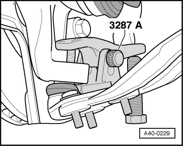
Unbolt drive shaft from gearbox flange shaft.
Vehicles with twelve-point nut
–
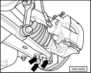
Mark positions of bolts securing swivel joint on suspension link.
–
Remove bolts -arrows-.
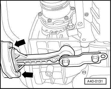
Vehicles with hexagon bolt
–
Unscrew nuts from swivel joint.
–
Install ball joint splitter as shown in illustration and press out swivel joint.
Note
Leave nut screwed on a few turns to protect thread on swivel joint.
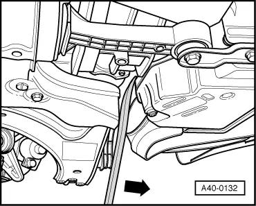
Continuation for all vehicles
–
Press out drive shaft.
–
In vehicles whose drive shaft is bolted using a hexagon bolt, additionally use the press tool -VW 434-.
Note
When pressing drive shaft out, ensure that there is sufficient clearance.
–
Remove drive shaft.
The drive shaft must not hang down!
The inner joint will otherwise be damaged through overflexing.
This procedure applies only to vehicles with an automatic gearbox.
–
Remove bolts -arrows-.
–
Remove left side of noise insulation if necessary.
–
Push engine/gearbox assembly forwards, e.g. with an assembly lever.
 Note
Note