volkswagen Workshop Repair Guides

Volkswagen Workshop Service and Repair Manuals

Assembly overview - crankcase > < Assembly overview - toothed belt drive
Removing and installing engine support
Special tools and workshop equipment required
t  Support bracket -10 - 222 A-
t  Torque wrench -V.A.G 1331-
   
–  Remove engine cover.
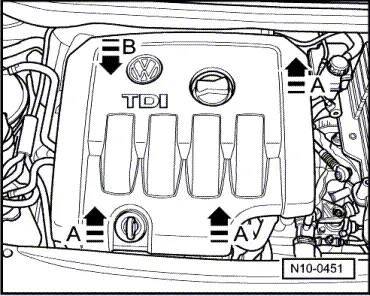
–  To do this, pull engine cover upwards abruptly at front and right -arrows A- and then pull forwards out of rear fastening -arrow B-.
  N10-0451
Two-piece engine cover
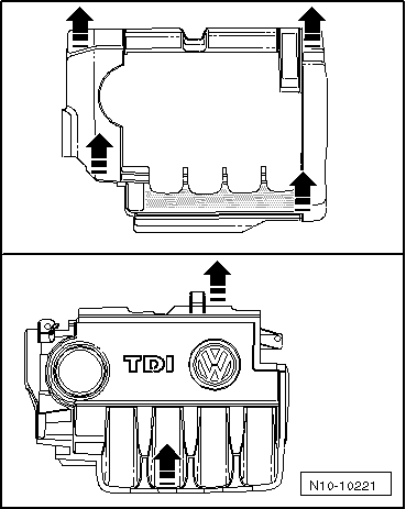
For two-piece engine cover, first pull outer engine cover abruptly upwards at -arrows-, then pull inner engine cover abruptly upwards at -arrows-.
  N10-10221
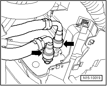
–  Separate push-on connectors of fuel lines -arrows-.
  Note
t  Do this by pressing in catch of push-on connectors.
t  Ensure that no fuel escapes (use a cloth).
–  Lay fuel filter with hoses to side.
–  Disconnect coolant hose from top of expansion tank.
–  Remove expansion tank and lay it to side.
–  Remove charge air pipe between charge air cooler and turbocharger.
–  Carefully cover or seal open ends.
Golf, Golf Plus and Touran:
  N15-10019
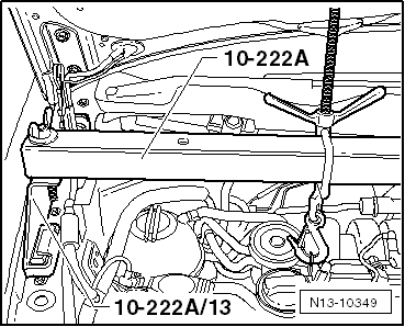
–  Fit engine support bracket -10-222A- with adapters -10-222A/13- and take up weight of engine in installation position.
  N13-10349
–  Remove securing bolts from assembly mounting/engine support -arrows- and remove complete assembly mounting.
  Note
t  The assembly mounting may only be removed if the engine is supported with support bracket 10-222A!
t  The engine support must only be loosened when the assembly mounting has been removed.
  WARNING
When raising and lowering engine using support bracket -10-222A-, ensure that no components or hoses are damaged, strained or torn off.
–  Remove noise insulation → General body repairs, exterior; Rep. gr.50.
–  Remove front right wheel housing liner.
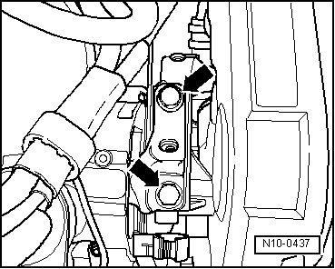
  N10-0437
–  Raise engine with support bracket -10-222A- until both upper bolts of engine support can be loosened and removed.
–  Lower engine with support bracket -10-222A- until lower bolt can be loosened and removed.
–  Remove engine support upwards.
Installing
–  Position engine support from above on cylinder block.
–  Insert new bolts and tighten by hand.
  Caution
The tightening sequence and specified torques for the engine support securing bolts must always be followed. Otherwise the engine support can be stressed and it can break.
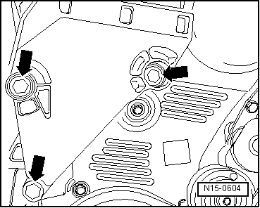
  N15-0604
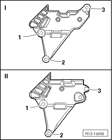
–  Tighten bolts for engine support in the sequence shown -1…3- to 40 Nm + (180°) turn further. To do this, raise or lower engine using support bracket -10 - 222 A-.
   I : Engine support with less clearance to engine
   II: Engine support with greater clearance to engine
  Note
Before installing assembly mounting, tighten all engine support bolts to prescribed torque.
–  Install assembly mounting between engine and body, renew securing bolts → Chapter.
  N13-10292
–  Bolt engine assembly mounting to engine support -arrows- by bringing contact surfaces together using support bracket -10-222A-. Specified torque: 60 Nm + turn 90° further.
Further assembly is basically the reverse of the dismantling sequence. In the process, note the following:
t  Ensure that fuel hose connections are tight.
t  Do not interchange supply line and return line (return line blue or with blue marking, supply line black).
t  When installing charge air pipes, ensure that locking lugs engage correctly.
–  Install wheel housing liner.
–  Install noise insulation. → General body repairs, exterior; Rep. gr.50.
  N10-0437

Assembly overview - crankcase > < Assembly overview - toothed belt drive