volkswagen Workshop Repair Guides

Volkswagen Workshop Service and Repair Manuals

Removing and installing toothed belt (vehicles with engine support with greater clearance to engine) > < Removing, installing and tensioning toothed belt
Removing and installing toothed belt (vehicles with engine support with less clearance to engine)
   
Removing and installing toothed belt (vehicles with engine support with less clearance to engine)
Special tools and workshop equipment required
t  Locking pin -3359-
t  2-hole pin wrench -T10020-
t  Locking pin -T10115-
t  Crankshaft stop -T10050-
t  Torque wrench (5…50 Nm) -V.A.G 1331-
t  Torque wrench (40…200 Nm) -V.A.G 1332-

   
t  Support bracket -10-222A- with adapters -10-222A/22- (for Golf, Golf Plus and Touran) or adapters -10-222A/1- (for Passat)
t  Counterhold tool -T10172- with pins -T10172/4-
t  Crankshaft stop -T10100- for vehicles with oval crankshaft belt pulley

  Note
Gradual introduction of oval crankshaft toothed belt pulleys. When installing this toothed belt pulley, the crankshaft stop -T10100- must be installed to determine the TDC position.
   
Characteristics of crankshaft belt pulley
  Note
  N15-10159
From model year 2004, a new toothed belt tensioner is installed. The tensioner has an additional hexagon hole -arrow-. To tension and release toothed belt, use Allen key instead of pin wrench -T10020-. This does not alter the procedure.
Removing
  Note
Adjustment work on toothed belts must be performed only on cold engines, as the indicator position on the tensioning element varies depending on the engine temperature.
  N15-10010
–  Remove engine cover.
To do this, pull engine cover upwards abruptly at front and right -arrows A- and then pull forwards out of rear fastening -arrow B-.
–  Remove poly V-belt → Chapter.
–  Remove poly V-belt tensioning element.
–  Remove upper toothed belt guard.
–  Remove front right wheel housing liner.
–  Remove exhaust pipe from auxiliary heater.
  N10-0451
–  Loosen connecting bolt for coolant pipe -arrow-.
–  Remove charge air pipe between charge air cooler and turbocharger.
–  Carefully cover or seal open ends.
–  Remove vibration damper/belt pulley.
–  Remove lower and centre toothed belt guards
–  Turn crankshaft to TDC No. 1 cylinder.
  Note
  N15-10018
Turn crankshaft until marking on crankshaft pulley and tooth segments of camshaft pulleys are on top. Marking on toothed belt guard must align with camshaft sender wheel -arrows-.
–  Lock crankshaft toothed belt pulley with crankshaft stop -T10050 bzw. T10100-. To do this, push crankshaft stop into teeth of belt pulley from face side.
  Note
The marks on the crankshaft toothed belt pulley and the crankshaft stop must align. When doing this, the pin of the crankshaft stop must insert in the drilling of the sealing flange.
  N15-0701
–  Separate push-on connectors of fuel lines -arrows-.
  Note
t  Do this by pressing in catch of push-on connectors.
t  Ensure that no fuel escapes (use a cloth).
–  Lay fuel filter with hoses to side.
–  Disconnect coolant hose from top of expansion tank.
–  Remove expansion tank and lay it to side.
Golf, Golf Plus and Touran:
  N15-10019
–  Fit engine support bracket -10-222A- with adapters -10-222A/22- and take up weight of engine in installation position.
Passat:
  N15-0687
–  Set up support bracket -10-222A- with legs -10-222A/1- and support engine in installation position, as shown.
Continuation for all vehicle types:
  N15-10175
–  Remove securing bolts from assembly mounting/engine support -arrows- and remove complete assembly mounting.
  Note
t  The assembly mounting may only be removed if the engine is supported with support bracket 10-222A!
t  The engine support must only be loosened when the assembly mounting has been removed.
  WARNING
When raising and lowering engine using support bracket -10-222A-, ensure that no components or hoses are damaged, strained or torn off.
  N10-0437
–  Raise engine with support bracket -10-222A- until both upper bolts of engine support can be loosened and removed.
–  Lower engine with support bracket -10-222A- until lower bolt can be loosened and removed.
  Note
The engine support can be removed only when toothed belt is slack.
–  Mark direction of rotation of toothed belt.
  N15-0604
–  Loosen camshaft pulley securing bolts -1 and 2- until camshaft pulleys can be turned in elongated holes.
–  Lock hubs using locking pin -3359-. To do this, slide locking pins through outer free elongated holes into holes in cylinder head.
–  Loosen tensioning roller securing nut.
  N15-0702
–  Turn pin wrench -T10020- anti-clockwise until toothed belt tensioning roller can be locked with locking pin -T10115-.
  N15-10037
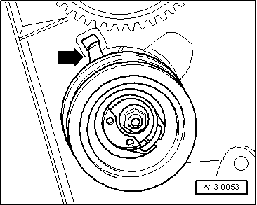
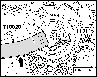
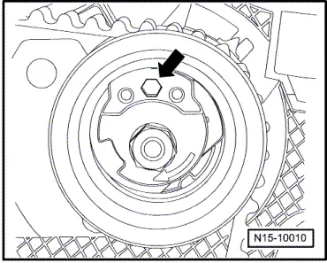
–  Now turn pin-wrench clockwise to stop and tighten securing nut -1- hand-tight.
–  Remove engine support downwards.
–  Remove toothed belt first from coolant pump and then from remaining pulleys.
Installing
  Caution
Strictly follow the procedure described here. If, for example, the final check is not performed and the locking tool is not fitted again, there is a danger that the timing is not correctly adjusted and the vehicle will exhibit engine running problems and rough idling.
  Note
t  Adjustment work on toothed belts must be performed only on cold engines, as the indicator position on the tensioning element varies depending on the engine temperature.
t  Specified torques → Chapter.
l  
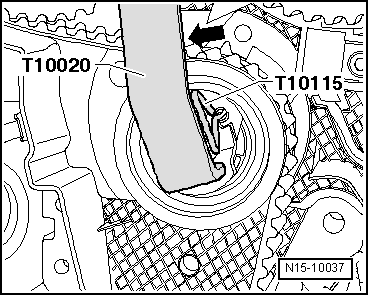
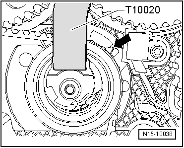
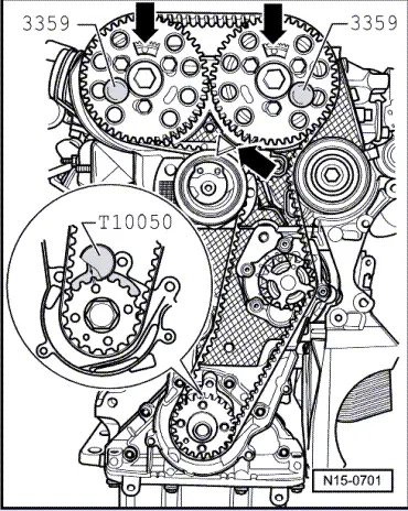
Tensioning roller must be locked with locking pin -T10115- and secured to right stop.
l  
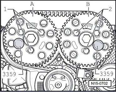
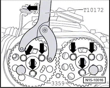
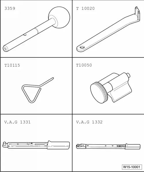
Camshafts are locked using diesel injection pump locking pin -3359-.
l  
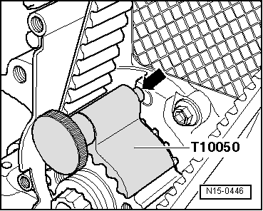
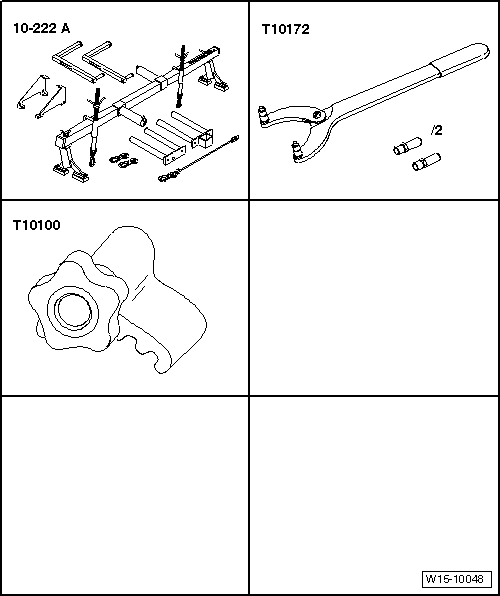
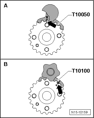
Crankshaft is locked using crankshaft stop -T10050 bzw. T10100-.
–  Turn camshaft pulleys in their elongated holes clockwise to stop.
–  Fit toothed belt to crankshaft pulley, tensioning roller and camshaft pulley and idler roller.
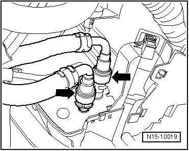
–  Then fit toothed belt on coolant pump toothed belt pulley.
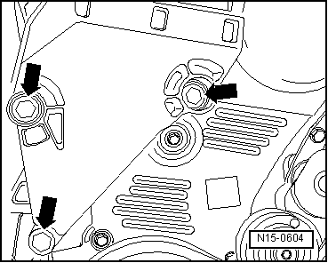
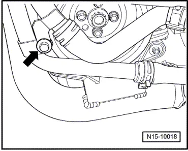
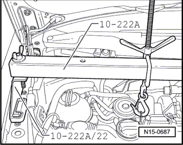
–  Install engine support from below and insert lower securing bolt.
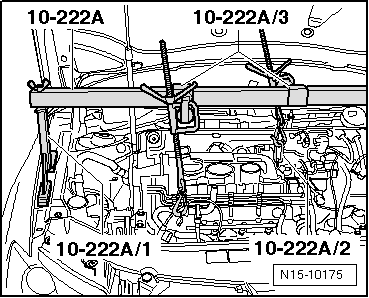
–  Raise engine with support bracket -10-222A- until indicator of tensioning roller can be seen.
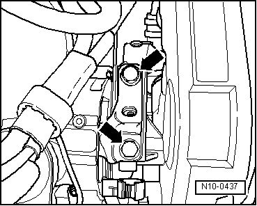
–  Loosen tensioning roller securing nut and pull out locking pin -T10115-.
  Note
  N15-10036
Ensure that tensioning roller seats correctly in rear toothed belt guard -arrow-.
  A13-0053
–  Now carefully turn tensioning roller clockwise using pin wrench until indicator is in middle of gap in base plate -arrow-.
Ensure that securing nut does not turn as well.
–  Hold tensioning roller in this position and tighten tensioning roller securing nut as follows: 20 Nm and 45° (1/8 turn) further.
  Note
When securing nut is tightened, indicator will turn maximum 5 mm to right out of base plate notch. This setting must not be corrected because the toothed belt will settle after it has run a while.
  N15-10038
–  Apply counterhold -T10172- as shown. Press counterhold -T10172- in direction of arrow keeping camshaft pulley under tension.
–  In this position, tighten camshaft pulley securing bolts -arrows- to 25 Nm.
–  Remove locking pins -3359- and crankshaft stop -T10050 bzw. T10100-.
–  Turn crankshaft at least two rotations in engine direction of rotation and set again to just before TDC No. 1 cylinder.
  N15-10016
–  Lock hub -A- by turning in engine direction of rotation until locking pin -3359- engages whilst turning.
–  Check whether:
t  Hub -B- can be locked using locking pin -3359-.
t  Crankshaft can be locked in position with crankshaft stop -T10050 bzw. T10100-.
t  Tensioning roller indicator is centred or maximum 5 mm to right of base plate notch.
If the hub -B- cannot be locked:
–  Loosen camshaft pulley -A- securing bolts -1-.
l  Hub -A- must be locked using locking pin -3359-.
  N15-0702
–  Turn crankshaft until hub of camshaft pulley -B- can be locked using locking pin -3359-.
–  Loosen camshaft pulley -B- securing bolts -2-.
  N15-0702
–  Turn crankshaft slightly against engine direction of rotation until the pin of the crankshaft stop is positioned just before the hole in the sealing flange -arrow-.
–  Now turn crankshaft in engine direction of rotation until crankshaft stop pin engages in sealing flange whilst turning.
  N15-0446
–  Apply counterhold -T10172- as shown. Press counterhold -T10172- in direction of arrow keeping camshaft pulley under tension.
–  In this position, tighten camshaft pulley securing bolts -arrows- to 25 Nm.
–  Remove locking pins -3359- and crankshaft stop -T10050 bzw. T10100-.
–  Turn crankshaft at least two rotations in engine direction of rotation and set again to just before TDC No. 1 cylinder.
–  Repeat check.
  N15-10016
–  Tighten bolts for engine support in the sequence shown -1…3- to 40 Nm + 1/2 turn (180 °) further. To do this, raise or lower engine using support bracket -10 - 222 A-.
   I : Engine support with less clearance to engine
   II: Engine support with greater clearance to engine
–  Install centre and lower parts of toothed belt guard.
–  Install belt pulley vibration damper: specified torque 10 Nm + 90° (1/4 turn) further.
  Note
Before installing assembly mounting, tighten all engine support bolts to prescribed torque.
–  Install assembly mounting between engine and body (renew securing bolts) → Chapter.
  N13-10292
–  Bolt engine assembly mounting to engine support -arrows- by bringing contact surfaces together using support bracket -10-222A-. Specified torque: 60 Nm + 90° (1/4 turn) further
–  Install lower part of toothed belt guard.
–  Install poly V-belt tensioning element: specified torque 25 Nm.
–  Install poly V-belt → Chapter.
Further assembly is basically the reverse of the dismantling sequence. In the process, note the following:
t  Ensure that fuel hose connections are tight.
t  Do not interchange supply and return lines (return line blue or with blue markings, supply line black).
t  When installing charge air pipes, ensure that locking lugs engage correctly.
–  Install wheel housing liner.
–  Install noise insulation tray. → General body repairs, exterior; Rep. gr.50.
  N10-0437

Removing and installing toothed belt (vehicles with engine support with greater clearance to engine) > < Removing, installing and tensioning toothed belt