volkswagen Workshop Repair Guides

Volkswagen Workshop Service and Repair Manuals

Checking vacuum unit for turbocharger > < Fitting hose connections with plug-in connectors
Removing and installing turbocharger
   
Removing and installing turbocharger
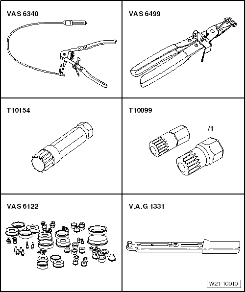
Special tools and workshop equipment required
t  Hose clip pliers -VAS 6340-
t  Hose clip pliers -VAS 6499-
t  Bit XZN 10 -T10154-
t  Bits -T10099-
t  Engine bung set -VAS 6122-
t  Torque wrench -V.A.G 1331-

  Caution
When a mechanical fault is found on the turbocharger, e.g. a destroyed compressor impeller, it is not only sufficient to renew the turbocharger. To prevent this from causing further damage, perform the following repairs:
t  Check air filter housing, air filter element and intake hoses for soiling.
t  Check complete charged air routing and charge air cooler for foreign objects.
If foreign objects are found in the charge air system, the charged air routing must be cleaned and the charge air cooler must be renewed, if necessary.
Removing:
–  Remove air filter housing → Chapter.
–  Remove noise insulation → General body repairs, exterior; Rep. gr.50
–  Remove front part of right wheel housing liner or front right wheel housing liner → General body repairs, exterior; Rep. gr.66.
–  Drain coolant → Chapter.
–  Remove engine cover.
   
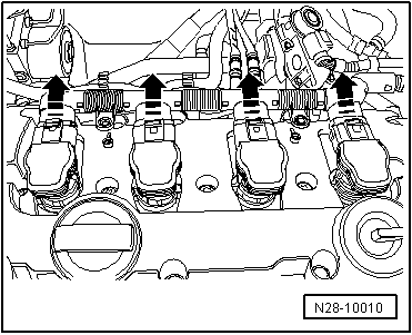
–  Pull connectors from ignition coils and lay wiring harness to side.
  N28-10010
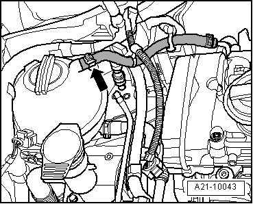
–  Disconnect coolant line to coolant expansion tank -arrow-.
  A21-10043
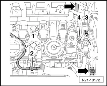
–  Separate vacuum pipe -1- at separating point -2- and lay pipe to side.
–  Remove coolant hoses -arrows- from coolant pipe.
–  Unscrew earth cable -3- (not engine codes CCZA, CCZB, CCZC, CCZD) and loosen bolt -4-.
  N21-10172
Engine codes BZB, CAWA, CAWB, CGYA, CCZA, CCZB, CCZC, CCZD, CDAA:
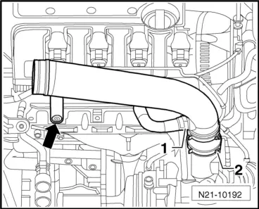
–  Press release tabs, detach air hose -1- and swivel to side.
–  Unscrew bolt -arrow- for air pipe.
–  Loosen hose clip -2- and remove air pipe.
  N21-10192
Engine codes CBFA, CCTA, CCTB:
–  Unscrew bolt -arrow- for air pipe.
–  Loosen hose clip -2- and place air pipe on cylinder head.
All:
–  Seal turbocharger with engine bung set -VAS 6122-.
  N21-10192
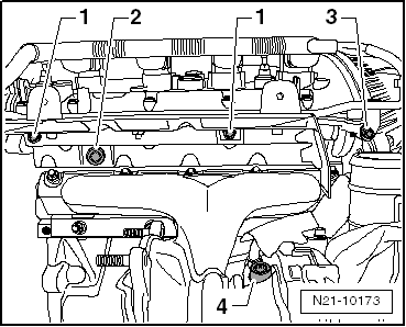
–  Unscrew bolts -1…3- and remove heat shield together with coolant pipe.
  Note
  N21-10173
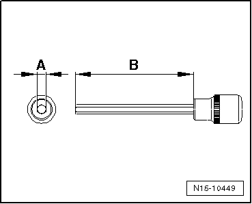
On 2.0 l engines, unscrew bolt -2- from heat shield using 6 mm -A- hexagon socket. The hexagon must be at least 5 cm -B- long. A socket which tapers to 6 mm at the tip is too thick.
  N15-10449
–  Remove oil supply line -4- from turbocharger.
  N21-10173
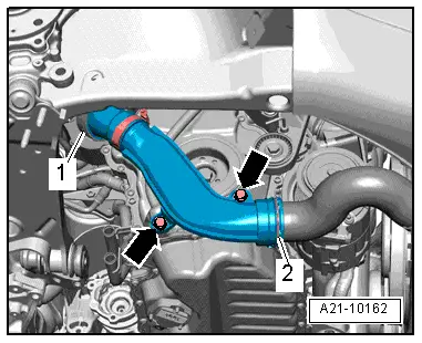
–  Remove bolts -arrows-.
–  Remove air pipe (lift clips -items 1 and 2-).
  A21-10162
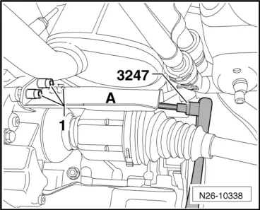
Vehicles with four-wheel drive:
–  Remove heat shield above right drive shaft.
  N26-10338
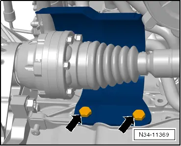
Vehicles with front-wheel drive
–  Remove heat shield for drive shaft on right side -arrows-.
All:
  N34-11369
–  Removing catalytic converters with front exhaust pipe → Chapter.
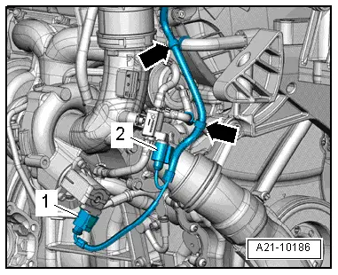
–  Separate electrical wiring connections -1 and 2- and place electrical wiring to one side -arrows-.
  A21-10186
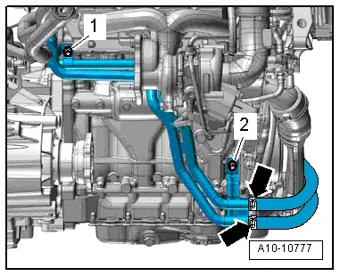
Vehicles with auxiliary heater:
–  Unscrew bolts -1 and 2- and move coolant pipes to the left.
  A10-10777
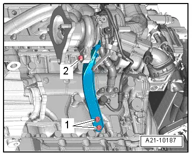
All vehicles:
–  Unscrew bolt -1- with bit XZN 10 -T10154-.
–  Unscrew bolt -2-.
  A21-10187
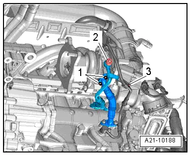
–  Remove banjo bolt -2- and move coolant pipe clear to one side.
Vehicles with front-wheel drive
–  Remove bolts -1- on oil return pipe.
Vehicles with four-wheel drive:
–  Undo and remove bolts of oil return line at crankcase.
All vehicles:
–  Remove bolt -3- on oil supply pipe.
  A21-10188
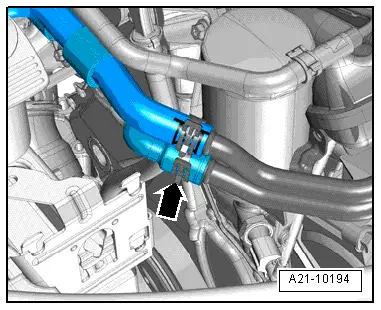
–  Disconnect coolant hose -arrow- and move it clear.
  A21-10194
–  Remove nuts -arrows-.
–  Remove turbocharger/exhaust manifold upwards.
Installing:
  Caution
When a mechanical fault is found on the turbocharger, e.g. a destroyed compressor impeller, it is not only sufficient to renew the turbocharger. To prevent this from causing further damage, perform the following repairs:
t  Check air filter housing, air filter element and intake hoses for soiling.
t  Check complete charged air routing and charge air cooler for foreign objects.
If foreign objects are found in the charge air system, the charged air routing must be cleaned and the charge air cooler must be renewed, if necessary.
Installation is carried out in the reverse order. When installing, note the following:
t  Installing hose connections with connector couplings → Chapter.
t  Renew seals, gaskets and self-locking nuts.
t  Fill turbocharger with engine oil at oil supply line connection.
t  After installing turbocharger, run engine for about 1 minute at idling speed to ensure that oil is supplied to turbocharger.
t  The coolant return line → Item must be installed together with the turbocharger.
t  Hose connections and hoses for charge air system must be free of oil and grease before assembly. The oil seal and sealing surface must only be oiled lightly for connector couplings → Chapter.
t  Secure all hose connections with hose clips which conform to production standard.
Specified torques → Chapter.
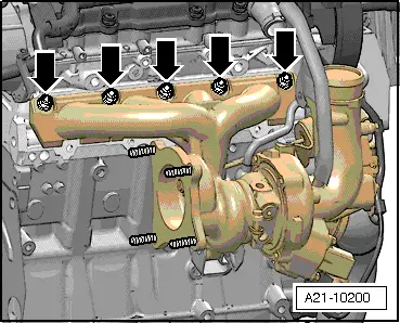
  A21-10200
Component Nm
Exhaust manifold/turbocharger to cylinder head 1) 2)Observe tightening sequence → Fig..
Oil supply line to turbocharger (M12 banjo bolt)33
Oil return line to turbocharger9
Coolant supply line to turbocharger (M14 banjo bolt)38
Turbocharger bracket to cylinder block 230
Turbocharger bracket to turbocharger 230
Air intake pipe (right side) to sump10
Heat shield to cylinder head M8 and M1220

1) Renew nuts.
2) Use high-temperature paste → ETKA (Electronic Parts Catalogue).
   

Checking vacuum unit for turbocharger > < Fitting hose connections with plug-in connectors