volkswagen Workshop Repair Guides

Volkswagen Workshop Service and Repair Manuals

Checking compression > < Removing toothed belt
Installing toothed belt
  Note
t  When camshaft is turned, crankshaft must not be at TDC. Danger of damage to valves and piston crowns.
t  The engine must be no more than warm to touch.
   
–  Set camshaft and crankshaft to TDC markings.
–  Place toothed belt on crankshaft pulley (observe DOR).
  N15-10329
–  Fit toothed belt in the sequence: tensioning roller, camshaft pulley, coolant pump and last onto idler roller -arrow-.
  Note
  N15-10143
Check that tensioning roller is seated correctly in cylinder head -arrow-.
  N15-10140
–  Tension toothed belt. To do so, turn hexagon key at the eccentric adjuster clockwise (direction of arrow) until the notch is above the indicator (toothed belt over-tensioned).
–  Then release tension on toothed belt.
–  Now tension toothed belt until the notch and the indicator are aligned.
–  Tighten securing nut to 25 Nm.
–  Turn crankshaft two turns in engine direction of rotation until engine is again at TDC. It is important that the last 45° rotation (1/8 turn) is performed without interruption.
–  Check toothed belt tension again. Specification: indicator and notch must align.
  N15-10139
–  Check valve timing. The markings must align -arrows-.
If the markings do not align:
–  Repeat valve timing adjustment.
If the markings align:
–  Bring engine bracket to installation position.
  Note
Do not yet tighten the securing bolts for the engine bracket. The engine bracket must sit “loosely” between engine and longitudinal member.
  N15-10329
–  Install toothed belt guard from below -arrows-.
–  Install belt pulley/vibration damper using new bolts. Specified torque: 10 Nm + 90° turn further.
  N15-10316
–  Check valve timing again: The markings must align -arrows-.
  N15-10314
–  Tighten the two upper bolts of toothed belt guard -arrows-.
–  Fit engine bracket on cylinder block and tighten upper bolts hand-tight.
  Note
  N15-10317
Note the different bolt lengths. Bolt -3- is about 25 mm shorter than bolts -1 and 2-.
–  Lower engine with support bracket -10-222A- until lower bolt -3- can be tightened.
–  Tighten all securing bolts to 45 Nm.
–  Lower engine to installation position.
–  Install engine assembly mounting. Specified torques → Chapter.
  N15-10144
–  Tighten bolts for engine assembly mounting and engine bracket hand-tight -arrows-; to do so, bring surfaces into contact using support bracket -10 - 222 A-.
–  Align engine mounting as follows:
  N10-0437
t  
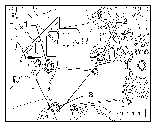
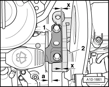
There must be a distance of -a- at least 10 mm between engine bracket and longitudinal member (right side).
t  The side surface of the engine bracket -2- should be located parallel to the support arm -1-.
–  Tighten bolts for engine assembly mounting and engine bracket. Specified torques: → Chapter.
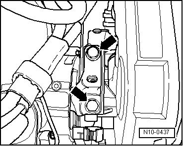
–  Remove support bracket -10 - 222 A-.
–  Install poly V-belt tensioner.
–  Install poly V-belt → Chapter.
–  Reconnect fuel and breather lines. Ensure that push-on connectors are properly secured.
–  Install coolant expansion tank and activated charcoal filter.
–  Resecure pendulum support to gearbox. Specified torques → Fig.
–  Install front right wheel housing liner → General body repairs, exterior; Rep. Gr.66.
–  Install noise insulation → General body repairs, exterior; Rep. Gr.50.
–  Refit fuse SC27 (Golf Plus SC47) in fuse holder.
  A10-1661

Checking compression > < Removing toothed belt