
Golf Mk5
| Coolant hose schematic diagram |
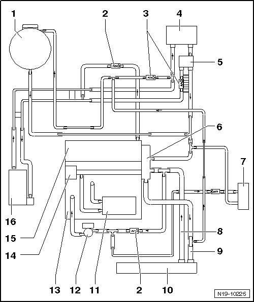
| 1 - | Expansion tank |
| 2 - | Non-return valve |
| q | Note installation position. |
| q | Arrow on non-return valve points in direction of flow |
| 3 - | Non-return valve |
| q | Integrated in coolant hose, not visible from outside |
| 4 - | Heat exchanger for heater unit |
| q | If renewed, refill system with fresh coolant. |
| 5 - | Heater coolant shut-off valve -N279- |
| q | Only vehicles with extra equipment |
| 6 - | Thermostat housing |
| 7 - | Gearbox oil cooler |
| q | Only vehicles with DSG® |
| 8 - | Lower coolant hose |
| 9 - | Upper coolant hose |
| 10 - | Radiator |
| 11 - | Oil cooler |
| q | For engine oil. |
| 12 - | Continued coolant circulation pump -V51- |
| 13 - | Cylinder block |
| 14 - | Coolant pump |
| 15 - | Cylinder head |
| 16 - | Auxiliary heater |
| q | Only vehicles with extra equipment |