volkswagen Workshop Repair Guides

Volkswagen Workshop Service and Repair Manuals

Removing and installing fan support with fans > < Coolant hose schematic diagram
Draining and filling coolant
   
Draining and filling coolant
Special tools and workshop equipment required
t  Refractometer -T10007-
t  Adapter for cooling system tester -V.A.G 1274/8-
t  Drip tray -V.A.G 1306- or drip tray -VAS 6208-
t  Torque wrench -V.A.G 1331-
t  Spring-type clip pliers -VAS 5024A-
t  Cooling system charge unit -VAS 6096-

Drain coolant:
  Note
t  Collect drained coolant in a clean container for re-use or disposal.
t  Observe waste disposal regulations.
  WARNING
Steam may escape when expansion tank is opened. Wear eye protection and protective clothing to avoid eye injuries and scalding. Cover cap with cloth and open carefully.
–  Carefully open cap on coolant expansion tank.
–  Remove noise insulation → General body repairs, exterior; Rep. gr.50
   
–  Release quick-release coupling -arrow- and remove lower coolant hose from radiator.
  N19-0276
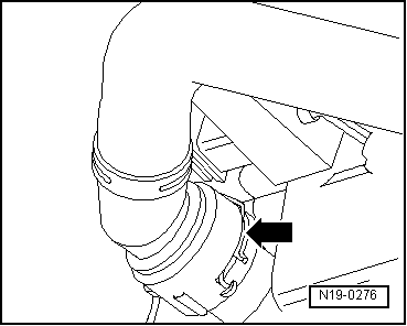
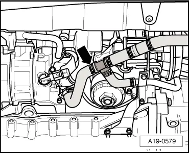
–  Remove additional bottom coolant hose to continued coolant circulation pump -V51--arrow- and allow remaining coolant to drain out.
  Note
Follow disposal regulations for coolant!
Filling with coolant:
  Caution
For mixing, only potable water may be used. Soiled water does not have the required quality to ensure the coolant's function.
  Note
t  In vehicles as of model year 2008, only G 12 plus-plus according to TL VW 774 G may be used as coolant additive.
t  Up to and including model year 2007, coolant additive G 12 plus according to TL VW 774 F and G 12 plus-plus according to TL VW 774 G can be used.
t  The coolant additive G 12 plus-plus can be mixed with the previous coolant additive G 12 plus. Identification: both are coloured purple.
t  Coolant additives marked „according to TL VW 774 G“ or „according to TL VW 774 F“ prevent frost, corrosion damage and scaling Such additives also raise the boiling point of the coolant. Therefore, the cooling system must be filled all year round with coolant additive.
t  Because of its higher boiling point, the coolant improves engine reliability under heavy loads, particularly in countries with tropical climates.
t  
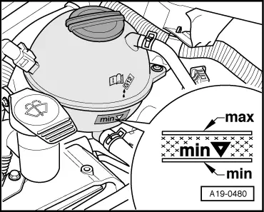
The frost protection must be guaranteed to approx. -25 °C. In countries with an arctic climate, to approx. -35 °C.
t  The coolant concentration must not be reduced by adding water even in warmer seasons and in warmer countries. The coolant additive concentration must be at least 40 %.
t  If a stronger anti-freeze mixture is necessary due to harsher weather conditions, it can be increased using G 12 plus-plus. It may only be strengthened, however, to 60 % (antifreeze protection to about -40 °C). Otherwise, the antifreeze protection will be reduced again and the cooling effect will be impaired.
t  
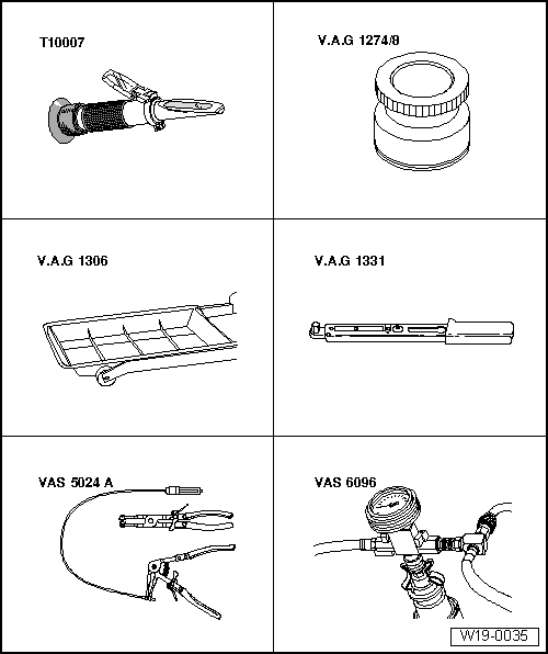
The refractometer -T10007- is recommended for determining the current anti-freeze density.
t  If radiator, heat exchanger, cylinder head or cylinder head gasket is renewed, do not reuse old coolant.
Recommended mixture ratios:
  A19-0579
Frost protection
to
Anti-freeze
proportion
G 12 plus-plus
G 12 plus → Remark
Tap water → Remark
-25 °C
-35 °C
40 %
50 %
3.6 l
4.5 l
5.4 l
4.5 l

1)  The quantity of coolant can vary depending upon vehicle equipment.
Procedure
   
–  Reconnect coolant hose to continued coolant circulation pump -V51--arrow-.
  A19-0579
–  Push lower coolant hose onto radiator union and secure.
–  Screw adapter for cooling system tester -V.A.G 1274/8- onto expansion tank.
–  Fill coolant circuit using cooling system charge unit -VAS 6096- → Operating instructions for cooling system charge unit VAS 6096.
  WARNING
Steam may escape when expansion tank is opened. Wear eye protection and protective clothing to avoid eye injuries and scalding. Cover cap with cloth and open carefully.
  N19-0276
–  Check coolant level and top-up if necessary. When the engine is at normal operating temperature, the coolant level must be at the upper mark; when the engine is cold, in the middle of the shaded field.
–  Install noise insulation → General body repairs, exterior; Rep. gr.50.
  A19-0480

Removing and installing fan support with fans > < Coolant hose schematic diagram