
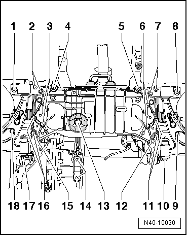
Golf Mk5
| Removing and installing anti-roll bar |

| Special tools and workshop equipment required |
| t | Locating pins -T10096- |
| t | Torque wrench -V.A.G 1332- |
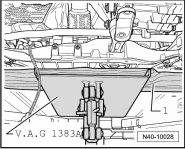
| t | Engine and gearbox jack -V.A.G 1383 A- |
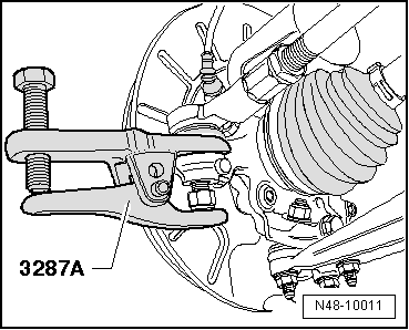
| t | Ball joint puller -3287 A- |
|
|
|
|
|
|
|
|
|
|
|
|
|
|
|
 Note
Note
|
|
| Specified torques |
| Component | Specified torque | ||||
Subframe to body
| 70 Nm + 90° | ||||
Bracket to body
| 70 Nm + 90° | ||||
Mounting bracket to body
| 70 Nm + 90° | ||||
Subframe to bracket
| 70 Nm + 90° | ||||
Swivel joint to cast steel suspension link
| 60 Nm | ||||
Swivel joint to sheet steel or forged aluminium suspension link
| 100 Nm | ||||
Anti-roll bar to coupling rod
| 65 Nm | ||||
Anti-roll bar to subframe
| 20 Nm + 90° | ||||
Suspension link to bracket
| 70 Nm + 180° | ||||
Steering box to subframe
| 50 Nm + 90° | ||||
Universal joint to steering box
| 30 Nm |
| Specified torques for pendulum support to gearbox |
 Caution
|
| Bolt | Specified torque | ||
M10 x 35 strength class 8.8
| 40 Nm + 90° further | ||
M10 x 35 strength class 10.9
| 50 Nm + 90° further | ||
M10 x 75 strength class 8.8
| 40 Nm + 90° further | ||
M10 x 75 strength class 10.9
| 50 Nm + 90° further |
|