
Golf Mk5
| Repairing subframe (front-wheel drive) |
| Special tools and workshop equipment required |
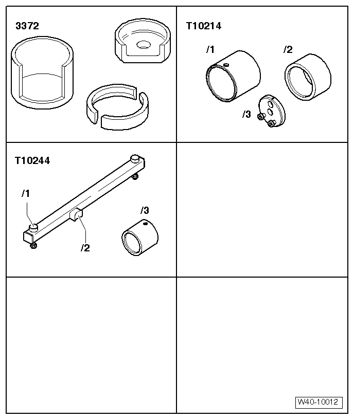
| t | Removal tool -3372- |
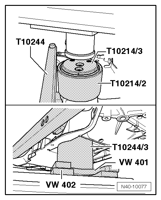
| t | Assembly tool -T10214- |
| t | Assembly tool -T10244- |
|
 Note
Note
|
|
|
|
|
|
Note |
|
|
|
Note
|
|
Note
|
|
|
|
|
|