volkswagen Workshop Repair Guides

Volkswagen Workshop Service and Repair Manuals

Checking swivel joint > < Repairing subframe (front-wheel drive)
Repairing subframe (four-wheel drive)
Special tools and workshop equipment required
   
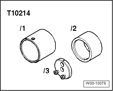
t  Assembly tool -T10214-
  W00-10076
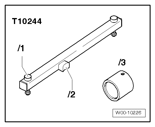
t  Assembly tool -T10244-
Pressing out bonded rubber bush
–  Remove subframe → Chapter.
  W00-10226
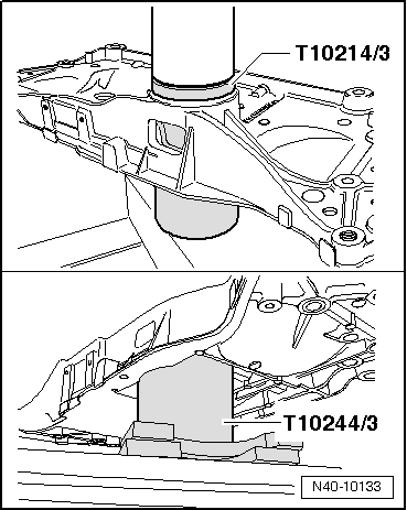
–  Press out both bonded rubber bushes at the same time as illustrated.
  Note
t  Chamfer of thrust piece-T10214/3- must point up.
t  Tube -T10244/3- has a larger and a smaller internal diameter. The subframe must lie against the larger internal diameter of the tube-T10244/3-.
Pressing in bonded rubber bush
  N40-10133
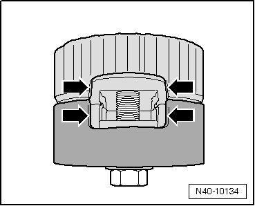
–  Bolt bonded rubber bushes together using original bolt, making sure that both notches -arrows- line up precisely.
  N40-10134
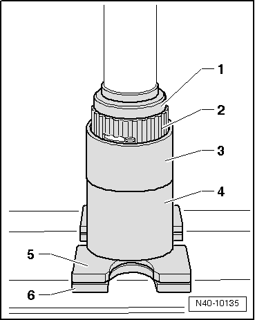
–  Insert assembled bonded rubber bushes with bolt head downwards into tube -T10214/2-.
1 - Thrust piece -T10214/3-
2 - Bonded rubber bush
3 - Tube -T10214/2-
4 - Tube -T10214/1-
5 - Thrust plate -VW 401-
6 - Thrust plate -VW 402-
  N40-10135
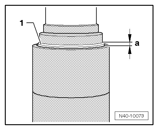
–  Press in bonded rubber bushes -1- until dimension -a- is obtained.
Dimension -a- = 2 - 3 mm.
  Note
  N40-10073
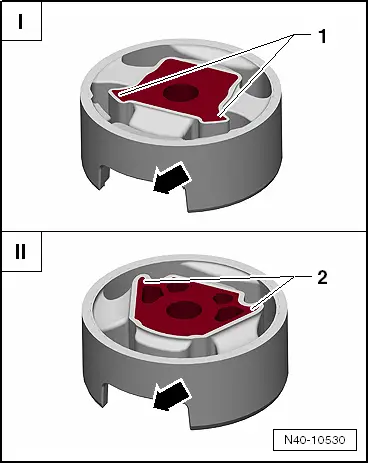
t  There are two different types of bonded rubber bushes for pendulum supports: the T version -I- and the V version -II-.
t  They are allocated by means of the → Electronic parts catalogue „ETKA“.
I - The corners of the inner core -1- point towards the opening for pendulum support -arrow- (T version)
II - The corners of the inner core -2- point away from the opening for pendulum support -arrow- (V version)
  N40-10530
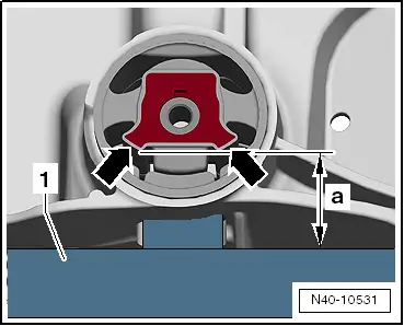
T-type bonded rubber bush
–  Align tube -T10214/2- with pressed-in bonded rubber bushes on subframe.
  Note
t  The corners of the inner core of the bonded rubber bush -arrows- must point towards the cross member -T10244--1-.
t  The corners of the inner core of the bonded rubber bush -arrows- must be parallel to the edge of the cross member -T10244--1-.
The distance -a- must be identical on the right and left to ensure parallel installation.
  N40-10531
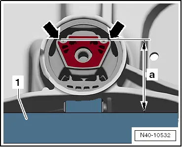
V-type bonded rubber bush
–  Align tube -T10214/2- with pressed-in bonded rubber bushes on subframe.
  Note
t  The corners of the inner core of the bonded rubber bush -arrows- must point away from the cross member -T10244--1-.
t  The corners of the inner core of the bonded rubber bush -arrows- must be parallel to the edge of the cross member -T10244--1-.
The distance -a- must be identical on the right and left to ensure parallel installation.
Continuation for both types:
  N40-10532
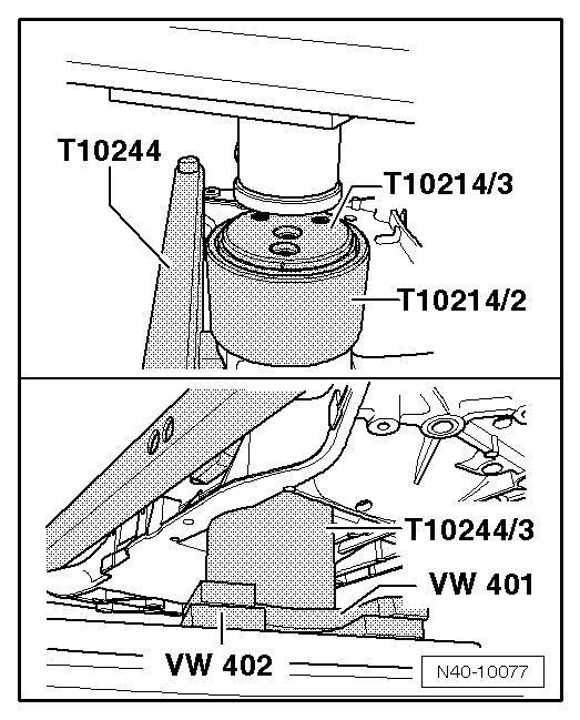
–  Position subframe against smaller internal diameter of tube-T10244/3-.
–  Press in bushes to stop and until a force of 20 kN is attained.
–  Detach assembly tool -T10244- from subframe and check pressed-in bonded rubber bushes for proper seating.
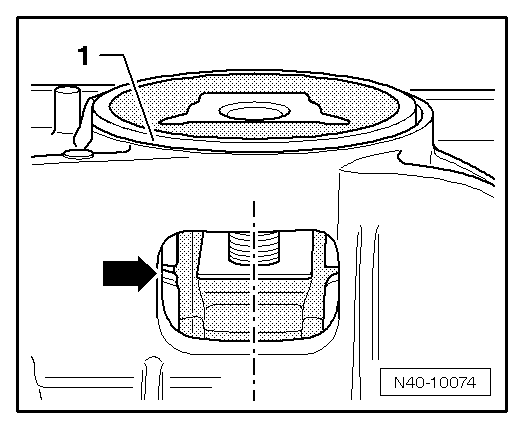
l  The recesses of the bonded rubber bushes must be positioned in the centre of the subframe opening.
  N40-10077
l  A gap -arrow- between the bonded rubber bushes is acceptable.
–  Install subframe → .
  N40-10074

Checking swivel joint > < Repairing subframe (front-wheel drive)