
Golf Mk6
|
|
|
|
|
|
|
|
|
|
|
|
|
|
|
|
|
 Caution
|
|
|
|
 WARNING
|
|
|
|
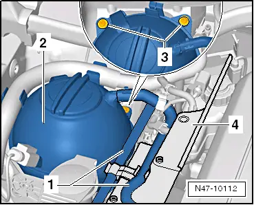
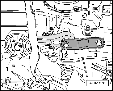
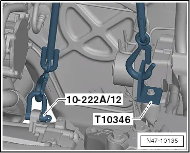
| – | Fit support bracket -10 - 222 A- and support engine/gearbox assembly. |

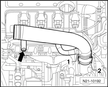
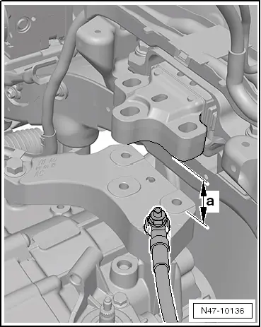
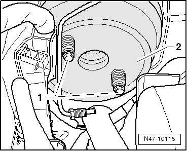
| – | Mount adapter -10 - 222 A /8- on the longitudinal beams directly before the projection -arrow 1- and next to the bolt -arrow 2-. |
|
|
|
|
|
|
|
|
 Note
Note
|
|
|
|