
Golf Mk6
| Connection diagram for coolant hoses in vehicles with auxiliary heating, engine codes BGU, BSE, BSF, CCSA, CMXA, CHGA |
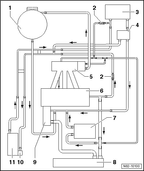
| 1 - | Coolant expansion tank |
| 2 - | Non-return valve |
| q | Note fitting position. |
| q | Arrow on non-return valve points in direction of flow. |
| 3 - | Heat exchanger for heater |
| 4 - | Heater coolant shut-off valve -N279- |
| t | Location: secured to engine compartment bulkhead |
| t | Removing and installing → Chapter |
| t | Not installed in vehicles with engine code CHGA. |
| 5 - | Intake manifold |
| 6 - | Cylinder head and cylinder block |
| 7 - | Engine oil cooler |
| 8 - | Radiator |
| 9 - | Coolant pump |
| 10 - | Circulation pump -V55- |
| q | Removing and installing → Chapter |
| 11 - | Auxiliary heater Thermo Top V |
| q | Removing and installing → Chapter |