
Golf Mk6
 Note
Note
|
|

|
 WARNING
|

|
|

|
Note
|

|
Note| When removing, observe lengths and location of bolts to ensure they are reinstalled in the correct position. |
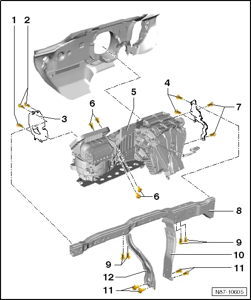
| 1 - | Bolt |
| q | 4.5 ± 0.7 Nm |
| q | Lower right on cable retainer to heater and air conditioning unit -VX1-, near plenum chamber bulkhead. |
| 2 - | Bolts |
| q | 4.5 ± 0.7 Nm |
| 3 - | Cable retainer |
| 4 - | Bolts |
| q | 9 ± 1.3 Nm |
| 5 - | Heater and air conditioning unit -VX1- |
| q | Removing: |
| – | Take condensation water drainage hose off heater and air conditioner unit -VX1- → Chapter. |
| – | Disconnect connectors from heater and air conditioner unit -VX1-. |
Note| t | Install all cable ties and other fasteners for wiring harness at the same places from which they were detached or cut when air conditioner was removed. |
| t | The air conditioning wiring harness is removed along with the heater and air conditioning unit -VX1-. |
| – | Remove bolts -6- and remove bracket. |
| – | Remove bolts -9-. |
| – | Unscrew bolts -4- and -7- and remove bracket. |
| – | Remove assembly carrier -8- → General body repairs, exterior; Rep. gr.70. |
| – | Unscrew bolts -1- and -2- from cable retainer -3-. |
Note| t | To reach bolt -1-, pull heater and air conditioning unit -VX1- on front passenger side away from bulkhead slightly. |
| t | When removing heater and air conditioner unit -VX1-, observe both coolant pipes to heat exchanger so that they do not catch at opening to plenum chamber or noise insulation tray and become bent or damaged. |
| t | Also observe wiring harness. Pulling it too hard could damage individual connections. |
| – | Remove heater and air conditioning unit -VX1-. |
| Installing: |
| Installation is carried out in the reverse order. When installing, note the following: |
Note| The aid of a second mechanic is required to install the heater and air conditioner unit -VX1-. |
| – | Have second mechanic guide both coolant pipes to heat exchanger through seal during installation of heater and air conditioning unit -VX1- (from engine compartment) → Fig.. |
| – | When installing, ensure that condensate drainage hose is seated correctly → Chapter. |
| – | Replenish coolant → Rep. gr.19. |
| – | Refilling with refrigerant R134a and refrigerant oil → Chapter. |
| 6 - | Bolts |
| q | 8 ± 1 Nm |
| 7 - | Bolts |
| q | 9 ± 1.3 Nm |
| 8 - | Assembly carrier |
| 9 - | Bolts |
| q | 9 ± 1.3 Nm |
| 10 - | Right support |
| 11 - | Bolts |
| q | 20 ± 3 Nm |
| 12 - | Left support |
Note
|

|