volkswagen Workshop Repair Guides

Volkswagen Workshop Service and Repair Manuals

Adjusting input shaft > < Assembly overview - input shaft
Dismantling and assembling input shaft
   
Dismantling and assembling input shaft
Special tools and workshop equipment required
t  Press tool -VW 407-
t  Thrust pad -VW 447 H-
t  Press tool -VW 412-
t  Tube -VW 422-
t  Pressure plate -VW 401-
t  Pressure plate -VW 402-
t  Press tool -VW 408 A-

   
t  Tube -VW 421-
t  Thrust piece -VW 454-
t  Thrust pad -VW 447 i-
t  Thrust pad -VW 510-
t  Drift sleeve -41-501-
t  -3-Splitter -Kukko 17/1-

   
Pressing out tapered roller bearing outer race
  V35-1116
Pressing in tapered roller bearing outer race
  V35-1117
Pressing off tapered roller bearing inner race
A - Splitter-Kukko 17/1-
  N35-0324
Pressing on tapered roller bearing inner race
  V35-1118
Pressing off gear wheel for 4th gear with tapered roller bearing and sleeve
  V35-1216
Pressing off gear wheel for 3rd gear
  V35-1217
Pressing on gear wheel for 3rd gear
  V35-1218
Pressing on gear wheel for 4th gear
Shoulder faces 3rd gear
  V35-1120
Pressing on tapered roller bearing inner race
  V35-1121
Pressing on sleeve for needle bearing
  N35-0019
Pressing out tapered roller bearing outer race
  N34-0665
Pressing in tapered roller bearing outer race
–  Install with shim after adjusting input shaft.
  V35-1124
5th gear synchronization
1 - Springs for lock pieces
2 - Locking collar with 3 recesses -arrows A- for the locking pieces -item 4-
3 - Synchro-hub
4 - Locking pieces - installation position: thin extension -arrow B- faces the pointed teeth of the locking collar -2-
  N35-0017
Assembling 5th gear locking collar/synchro-hub
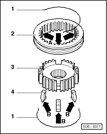
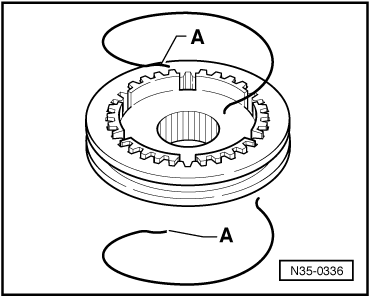
–  Slide locking collar over synchro-hub.
Pointed teeth -A- and shoulder -B- of synchro-hub face in same direction. The recesses for the locking pieces in locking collar and synchro-hub must be aligned ( → Fig.).
–  Insert locking pieces (installation position → Fig.).
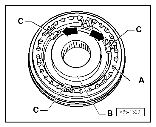
–  Install springs below shoulder -C- of the locking piece, offset 120°.
Installation positions of springs if locking pieces are not hollow:
Spring must seat with angled end in front of locking piece -arrows-.
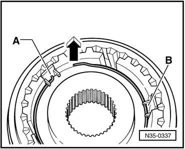
Installation positions of springs if locking pieces are hollow:
–  Angled end of spring must locate in hollow locking piece (⇒ second figure below).
  V35-1320
Installing springs with bent ends -A-
These springs are installed on both sides.
–  Spring are installed only in conjunction with hollow locking pieces.
–  Insert locking pieces (installation position → Fig.).
  N35-0336
Installation position of springs
–  Install springs offset 120°.
–  Angled end -A- of spring must locate in hollow locking piece.
It must be located under shoulder -B- of locking piece.
Bent ends always face away from synchro-hub -direction of arrow-.
  N35-0337

Adjusting input shaft > < Assembly overview - input shaft