
Golf Mk6
| Dismantling and assembling input shaft |
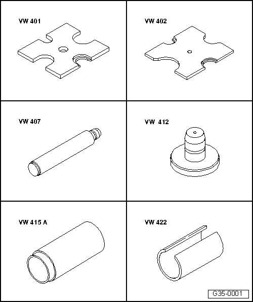
| Special tools and workshop equipment required |
| t | Pressure plate -VW 401- |
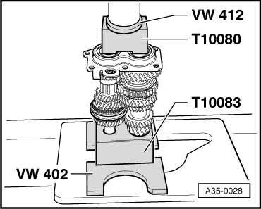
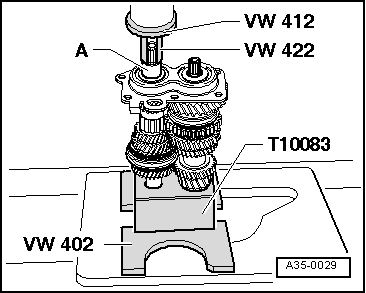
| t | Pressure plate -VW 402- |
| t | Press tool -VW 407- |
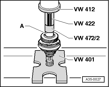
| t | Press tool -VW 412- |
| t | Tube -VW 415 A- |
| t | Tube -VW 422- |

| t | Spacer sleeve -VW 472/2- |
| t | Tube -VW 516- |
| t | Drift sleeve -30-100- |
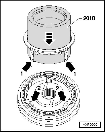
| t | Tube -2010- |
| t | Thrust piece -3002- |
| t | Thrust piece -T10080- |

| t | Thrust piece -T10081- |
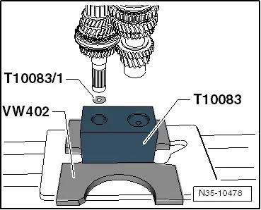
| t | thrust piece -T10083- |
| t | Washer -T10083/1- |
| t | Pressure plate -T10084A- |
| t | -1-Internal puller -Kukko 21/5- |
| t | -2-Puller -Kukko 18/1- |
| t | -3-Splitter -Kukko 17/1- |
| t | -4-Counter support -Kukko 22/1- |
 Note
Note| t | When installing new gears or new input shaft, refer to → Electronic parts catalogue „ETKA“ and technical data. |
| t | Install all bearings, synchromeshed gears and synchro-rings on input shaft with gear oil. |
| t | Do not interchange synchro-rings. When reusing always fit to the original gear. |
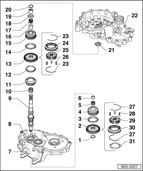
| 1 - | Retaining ring |
| q | Always renew |
| q | Determining thickness → Anchor |
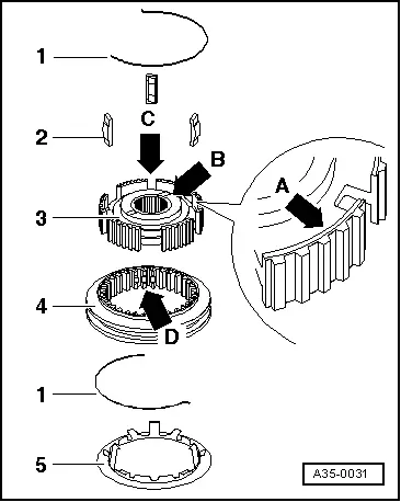
| 2 - | 5th gear locking collar with synchro-hub |
| q | Removing and installing → Chapter |
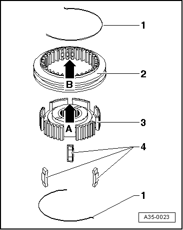
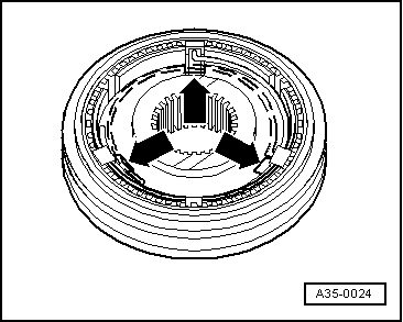
| q | Dismantling → Fig. |
| q | Assembling 5th gear locking collar/synchro-hub |
| q | Installation position → Fig. |
| 3 - | Synchro-ring for 5th gear |
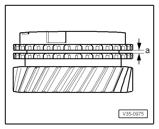
| q | Check for wear → Fig. |
| 4 - | Synchromeshed gear for 5th gear |
| 5 - | Needle bearing |
| q | For 5th gear |
| q | Renew together with → Item |
| 6 - | Sleeve |
| q | For 5th gear needle bearing |
| q | Renew together with → Item |
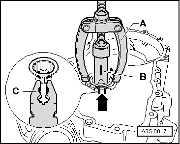
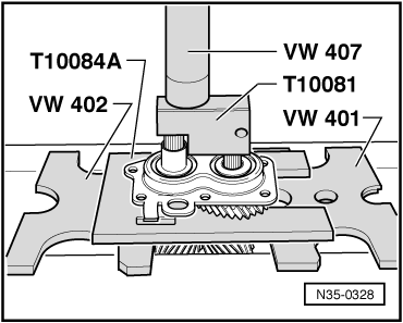
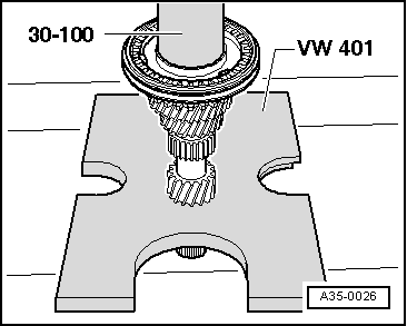
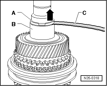
| q | Press off with bearing mounting with deep groove ball bearing → Fig. |
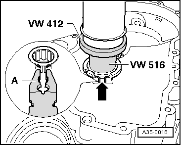
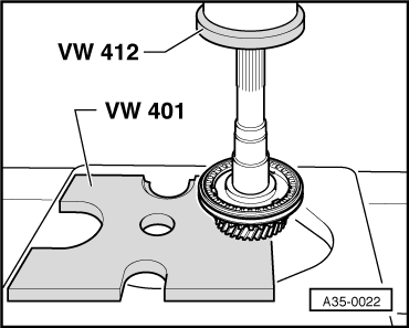
| q | Pressing on → Fig. |
| 7 - | Gearbox housing |
| q | Repairing → Chapter. |
| 8 - | Bearing mounting with deep groove ball bearing |
| q | Renew deep groove ball bearing only together with bearing mounting |
| q | If bearing mounting is separated from gearbox housing, then mounting must always be renewed. |
| q | Pressing off → Fig. |
| q | Pressing on → Anchor |
| 9 - | Input shaft |
| 10 - | Needle bearing |
| q | For 3rd gear |
| 11 - | Synchromeshed gear for 3rd gear |
| 12 - | Synchro-ring for 3rd gear |
| q | Check for wear → Fig. |
| 13 - | Locking collar with synchro-hub for 3rd and 4th gear |
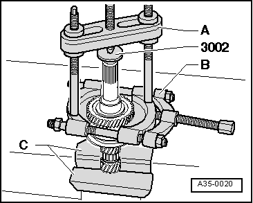
| q | Press off with synchromeshed gear for 3rd gear → Fig. |
| q | Dismantling → Fig. |
| q | Installation position, locking collar and synchro-hub → Fig. |
| q | Assembling → Fig. |
| q | Pressing on → Fig. |
| 14 - | Synchro-ring for 4th gear |
| q | Check for wear → Fig. |
| 15 - | Synchromeshed gear for 4th gear |
| 16 - | Sleeve |
| q | For 4th gear needle bearing |
| q | Renew together with → Item |
| q | Removing → Fig. |
| 17 - | Needle bearing |
| q | For 4th gear |
| q | Renew together with → Item |
| 18 - | Thrust washer |
| 19 - | Inner race for cylindrical roller bearing |
| q | Removing → Fig. |
| q | Pressing on → Fig. |
| 20 - | Retaining ring |
| q | Always renew |
| q | Determining thickness → Fig. |
| 21 - | Cylindrical roller bearing |
| q | With retaining ring |
| q | Pulling out → Fig. |
| q | Pressing in → Fig. |
| q | Installation position: retaining ring in bearing faces input shaft |
| 22 - | Clutch housing |
| q | Repairing → Chapter. |
| 23 - | Spring |
| q | Installation position → Fig. |
| 24 - | 3rd and 4th gear locking collar |
| 25 - | 3rd and 4th gear synchro-hub |
| 26 - | Locking pieces (Qty. 3) |
| 27 - | Spring |
| q | Installation position → Fig. |
| 28 - | Locking pieces (Qty. 3) |
| 29 - | Synchro-hub for 5th gear |
| 30 - | Locking collar for 5th gear |
| 31 - | Stop ring |
| q | Prevents locking pieces from drifting out |
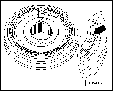
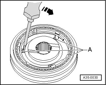
| q | Removing → Fig. |
| q | Installing → Fig. |
|
|
|
|
|
|
|
|
|
|
|
|
|
|
|
|
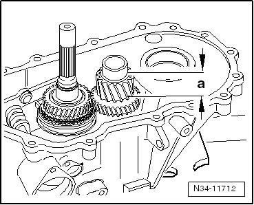
| Gap -a- | Installation dimension | Wear limit |
| 3rd, 4th and 5th gears | 1.1…1.7 mm | 0.5 mm |
|
|
|
|
Note
|
|
| Measured value (mm) | Retaining ring thickness (mm) | Axial play (mm) |
| 0.05 … 0.14 | 2.0 | 0.05 … 0.15 |
| 0.15 … 0.24 | 2.1 | 0.05 … 0.15 |
| 0.25 … 0.34 | 2.2 | 0.05 … 0.15 |
| 0.35 … 0.44 | 2.3 | 0.05 … 0.15 |
| 0.45 … 0.51 | 2.4 | 0.05 … 0.10 |
Note |
|
|
| Dimension -a- = 30.6 mm | |
| Insert shim -T10083/1- ⇒ next figure. |
|
|
|
|
|
|
|
|
|
|
|
|
|
|